Brewmatic – Design
I present Brewmatic: a compact, mobile, electric, fully digital, internet connected, voice enabled, 3-stage home brewery.
To read about the motivations behind the beautiful machine, read Brewmatic – Introduction and Problem Statement.
Requirements
The simplified must-haves for Brewmatic:
- Must store within the dimensions of a storage locker that is 74″ tall x 69″ long x 45″ wide.
- Must draw power safely from a single 240V range receptacle.
- Fresh water must be drawn from standard residential taps.
- Waste water must be expelled through standard residential drains.
- Steam must be exhausted to the exterior of the dwelling without condensing and causing leaks inside.
- Must model the traditional 3-stage brewery: Hot Liquor Tank, Mash Tun and Boil Kettle.
- The temperature at each stage of brewing must be controllable and maintainable within 1 degree F.
- Must provide user interfaces through PC, mobile and voice.
High Level Design

- Hot Liquor Tank (HLT)
- Mash Tun (MT)
- Boil Kettle (BK)
- Pumps
- Counter flow wort chiller
- Control unit
- Steam exhaust
- Boil Kettle exhaust lid
- Part storage
- Chemical and glassware storage
- Specialty grain storage
- Grain mill
- Temperature probes
- Drip shelf
- Accessory storage/drying hooks
Brewmatic uses of off-the-shelf components where feasible. In favor of panel mounted PID controllers, as often used in electric breweries, a microcontroller is used with bespoke firmware to reduce cost and space. As a full description of each component would require its own post, a summary of each follows below.
Hardware
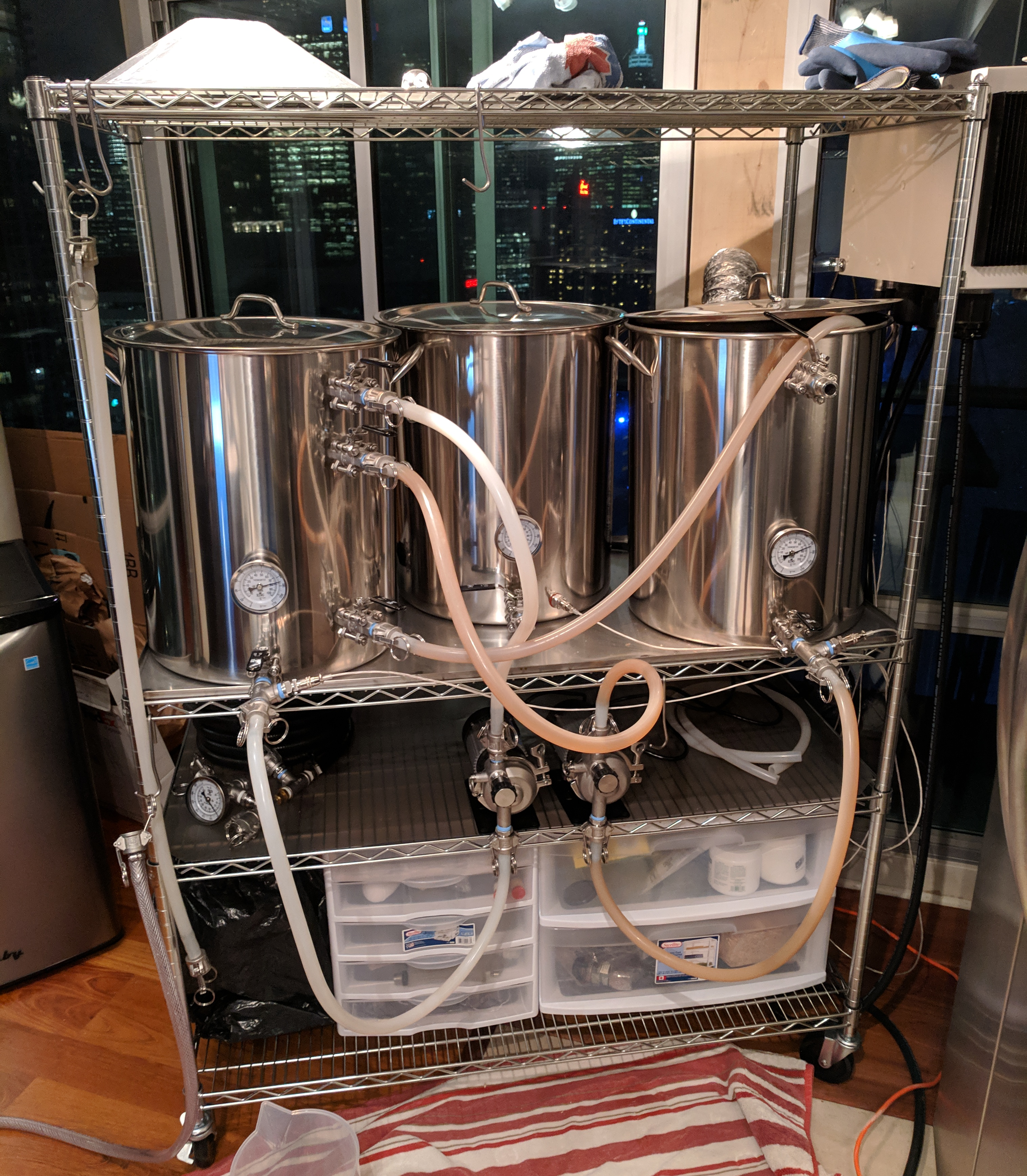
Components are mounted on a standard food service wire shelving cart. The first shelf provides storage for parts, grain, mill, oxygen, chemicals, tools and glassware. The second stores hoses, pumps, exhaust vents and the control unit (when not in use). The top shelf primarily acts as a mounting point for the control unit, exhaust venting and brew day accessories.

The third shelf provides a rigid, heat tolerant, and spill proof surface for the heavy (when filled) Hot Liquor Tank (HLT), Mash Tun (MT), and Boil Kettle (BK). An 18-gauge, 304 stainless steel sheet was creased at the edges then welded to the stock wire frame shelf. These edges keep spilled liquid from cascading down to the lower shelves (a hard lesson). The sheet also greatly increases the strength of the shelf. Without it, a full pot dramatically warps the wire shelf downwards, so much that it is difficult to take liquid readings from the pot’s inside markings.
All metal hardware (pots, tubing, fitting, couplers, valves, etc.) is 304 stainless steel. All three pots are fitted with PT100 temperature probes and ball valves.
Hot Liquor Tank – 15 Gallons
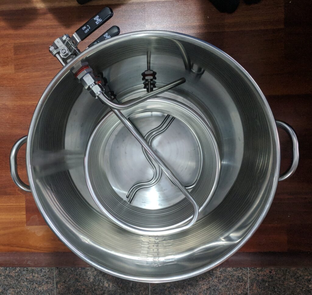
A 25ft steel coil exchanges heat between hot water inside the pot and wort recirculating to/from the MT. A stainless hot water tank heating element provides direct contact heat. The HLT is “stirred” using recirculation to maintain a uniform temperature. Water is pumped from the valve at the pot’s bottom to the right angle tube mounted at the top.
Mash Tun – 10 Gallons
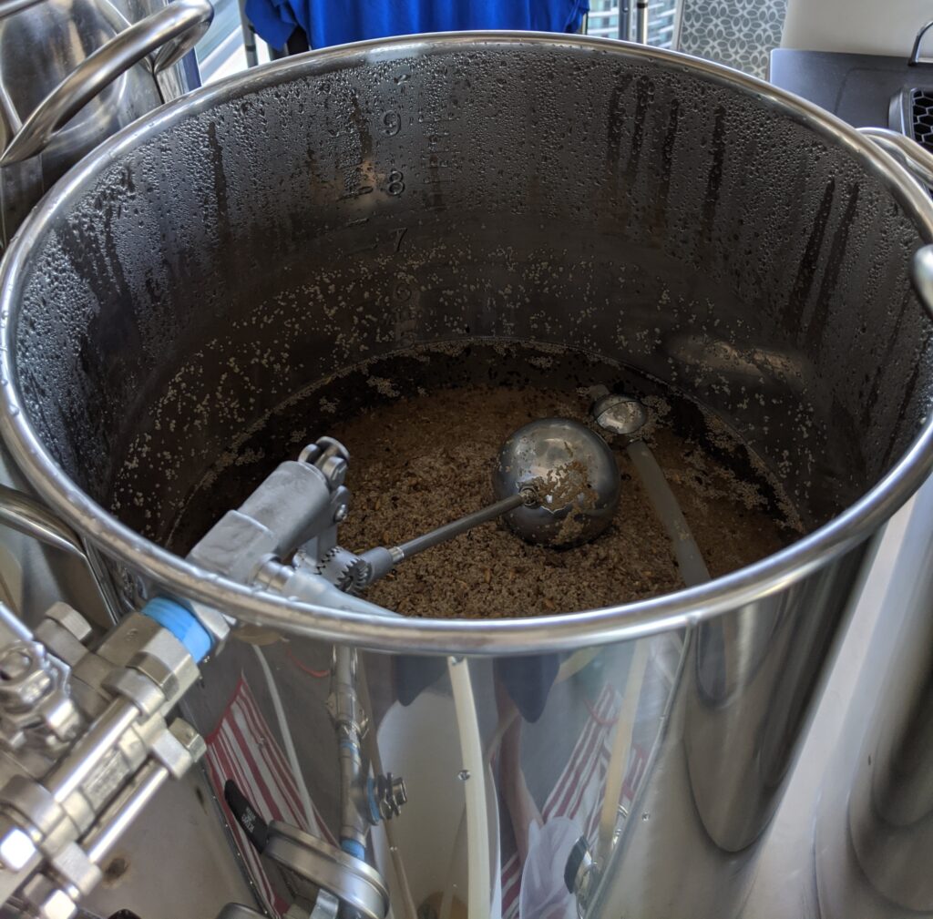
A Blichmann AutoSparge is used to control recirculation rates during the sparge. It was necessary to down size the MT from 15 gallons (pictured at top of post) to 10 for reliable control over the liquid level above the grain bed. If the pot is too large, more liquid is required to keep the grain bed below the surface than is optimal. The AutoSparge needs enough head room to float and perform properly.
A standard convex, perforated, steel plate provides the false bottom.
Boil Kettle – 15 gallons
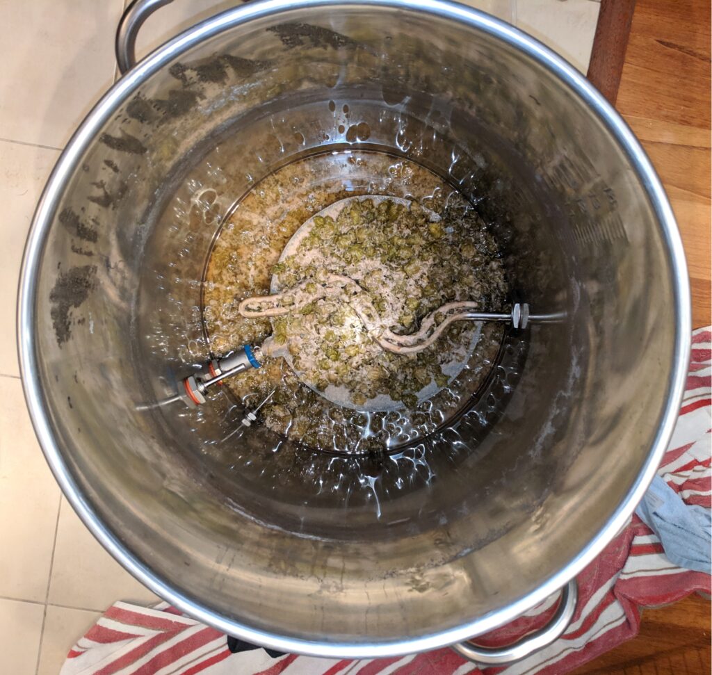
A stainless “pancake” filter sits below another stainless hot water tank heating element. Inside the pancake filter is a stainless straw, bent slightly, and pointed towards the bottom of the pot to minimize dead space.
Plumbing
1/2″ camlock couplers are used between all hose connections. 1/2″ silicon tubing is used for all liquids, with the exception of fresh water. This is braid reinforced PVC for connection (also camlock) to a high pressure household water faucet. Two Blichmann RipTide pumps are used to transfer/recirculate between the HLT/MT and MT/BK. Cooling is accomplished using a 25ft counter-flow wort chiller and tap water.
Electrical
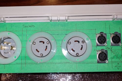
The only 240V source available in the unit is from the range (stove). I couldn’t find anything off-the-shelf that converts a range outlet to a 4 wire GFCI. So I built one with a spa panel (Siemens) from Costco, a NEMA 14-50R from Home Depot and a NEMA L6-30R from Amazon. The beauty of this solution is the ability to keep the stove plugged in.
This powers the heating elements (240VAC) in the HLT and MT, pumps (120VAC) and control circuitry (3/5VDC).
Control
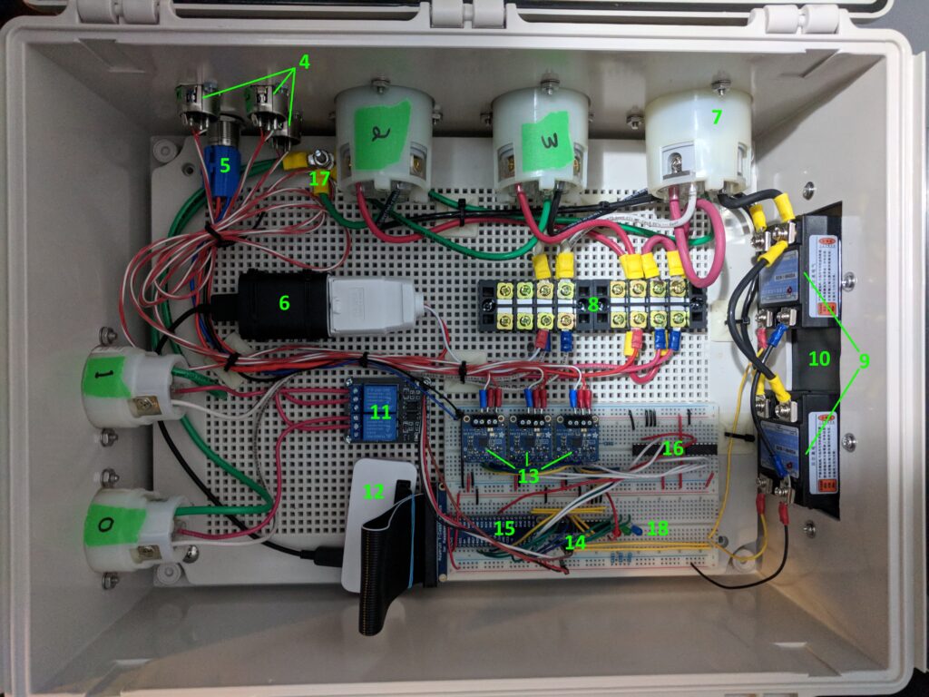
Digital control of the system is handled by a Raspberry Pi Zero (12, see Firmware below). Pulse-width modulation controls the duty cycle of the heating elements (2, 3) via solid-state relays (9). Temperature for each of the HLT, MT and BK are read through PT100 sensors (4) connected to the I2C bus (13). Automotive relays (11) provide control of the pumps.
- Hot Liquor Tank Pump 120V out receptacle
- Mast Tun Pump 120V out receptacle
- Hot Liquor Tank 240V out receptacle
- Boil Kettle 240V out receptacle
- Temperature probe receptables
- Master power switch
- 120VAC to 5VDC converter
- 240VAC in receptacle
- 120VAC bus bars
- Boil Kettle/Hot Liquor Tank solid state relays
- Heat sink
- Pump relays
- Raspberry Pi Zero
- PT100 drivers
- I/O multiplexing logic
- Raspberry Pi I/O expander
- Safety logic, prevents activating both solid state relays simultaneously
- Common ground
- Debug LEDs
Firmware
A C++ driver performs the following basic input/output functions:
- Toggle pumps on/off
- Heating element power (in percent) via pulse width modulation
- Read temperature probes
This driver is used by a multi-threaded Python application to control the system in response to commands from the user via the cloud. The application reports changes in state back to the cloud for user visibility. For example: confirmation that HLT pump is on, or temperature changes while the HLT is heating up.
The C++/Python split was chosen for rapid development and testing. The Pi Zero is quite capable of running Python code without becoming resource constrained.
Cloud
Cloud infrastructure is hosted on AWS. IoT device shadows are used to communicate state/settings to/from the device and the user interface. The IoT Python SDK makes it easy to integrate secure communication on the Pi Zero.
Visual User Interface
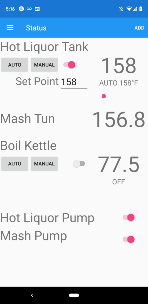
Xamarin was selected as the UI framework for the following reasons:
- I didn’t want to write separate iOS and Android code.
- Xamarin provides a Windows UI (bonus).
- There is some support for the AWS IoT SDK.
- I wanted to re-learn C#.
The UI renders well on all of Windows, iOS and Android.
Voice User Interface
Using AWS as a cloud provider made it easy to develop an Alexa Skill to control the system verbally. Also, I happened to work in Alexa, writing a skills SDK, at the time.
The voice interface lets a user query for temperature of the HLT, MT or BK. They can also turn on pumps or change the set point of the HLT or BK. This is extremely helpful when the brewers hands are busy, which is always!

You May Also Like
2,132 Comments
Tools For Creators
I am really inspired along with your writing talents and also with the format for your weblog. Is that this a paid subject or did you modify it yourself? Anyway stay up the nice quality writing, it’s uncommon to look a nice weblog like this one nowadays. !
TestUser
seshtFIN xZYZuC FLgFr
TestUser
McVLy fpnn VoPVyvf ZioTEGHx wYhPubf wcqKlTuk
John
tNmS qthnZw cxC vMRo ySmSgyT QIWWFku
Christian1715
http://passo.su/forums/index.php?autocom=gallery&req=si&img=4159
Alaina2104
https://mazda-demio.ru/forums/index.php?autocom=gallery&req=si&img=6414
Donald2341
Very good https://is.gd/tpjNyL
TommymuB
hi
Jocelyn436
https://myteana.ru/forums/index.php?autocom=gallery&req=si&img=6819
Bella4186
https://honda-fit.ru/forums/index.php?autocom=gallery&req=si&img=7236
Jed2076
https://vitz.ru/forums/index.php?autocom=gallery&req=si&img=4814
Gretchen3339
https://myteana.ru/forums/index.php?autocom=gallery&req=si&img=6763
Clara4614
https://myteana.ru/forums/index.php?autocom=gallery&req=si&img=6747
Angelo3642
https://myteana.ru/forums/index.php?autocom=gallery&req=si&img=6787
Emilie58
https://honda-fit.ru/forums/index.php?autocom=gallery&req=si&img=7200
Derrick594
http://wish-club.ru/forums/index.php?autocom=gallery&req=si&img=5345
Veronica409
http://terios2.ru/forums/index.php?autocom=gallery&req=si&img=4677
Clint2245
https://mazda-demio.ru/forums/index.php?autocom=gallery&req=si&img=6474
Laura4869
https://honda-fit.ru/forums/index.php?autocom=gallery&req=si&img=7081
Lauryn1807
https://vitz.ru/forums/index.php?autocom=gallery&req=si&img=4863
Emilie2555
https://myteana.ru/forums/index.php?autocom=gallery&req=si&img=6666
xmc.pl
Reading your post is like a journey through a picturesque landscape of thought – full of color, depth, and light! If you ever decide to publish a book, you’ll surely find a devoted audience waiting for it!
Charlesitede
Hello,
Exclusive promo quality music for DJs https://sceneflac.blogspot.com
MP3/FLAC, label, music videos. Fans giving you full access to exclusive electronic, rap, rock, trance, dance… music.
0day team.
Jimmy1720
https://hrv-club.ru/forums/index.php?autocom=gallery&req=si&img=7168
Adria1352
http://wish-club.ru/forums/index.php?autocom=gallery&req=si&img=5249
Harrison1283
https://vitz.ru/forums/index.php?autocom=gallery&req=si&img=4838
Lynne3792
https://myteana.ru/forums/index.php?autocom=gallery&req=si&img=6659
Aniya3607
http://passo.su/forums/index.php?autocom=gallery&req=si&img=4283
Maggie929
Tanir & Tyomcha – Да Да Да скачать песню и слушать бесплатно https://shorturl.fm/NnM4W
Kingston1288
Anton Verkhotin & Антон Верхотин – Загрустила скачать песню и слушать бесплатно https://shorturl.fm/YGtey
Hailey994
The Коля – Идивжнапмж скачать и слушать песню https://shorturl.fm/PFLTA
Cara1697
Вика Воронина – Зажигай, Детка! скачать песню и слушать онлайн https://shorturl.fm/OYe6v
Katelyn3724
ФОГЕЛЬ – ПУЛЯ скачать и слушать песню https://shorturl.fm/Mh9SJ
Kenny2531
Gidayyat & Gazan – Коронаминус скачать песню в mp3 и слушать онлайн https://shorturl.fm/PDWO7
Anastasia4571
Marina – Кино скачать mp3 и слушать бесплатно https://shorturl.fm/we49t
Harry99
Егор Крид, The Limba – Coco L’Eau скачать песню и слушать бесплатно https://shorturl.fm/a2G6Q
Elijah3570
Мот – Перемены-это красиво скачать песню и слушать бесплатно https://shorturl.fm/sc09i
sxpksgyfhw
qlmkhuueoeslntnfmikyxepgmyomfo
jnpljtztqj
zsxlqrowwkvhfeqervjifmwkikmoyk
📈 Email; Process 1,236437 BTC. Confirm => https://yandex.com/poll/7R6WLNFoDWh6Mnt8ZoUfWA?hs=5ff75b51b205032386e9a0ddf68362c3& 📈
tr4b34
Ivan2608
https://mazda-demio.ru/forums/index.php?autocom=gallery&req=si&img=6528
Angelo4904
https://hrv-club.ru/forums/index.php?autocom=gallery&req=si&img=6904
Zane2543
https://vitz.ru/forums/index.php?autocom=gallery&req=si&img=4939
Kate4330
https://myteana.ru/forums/index.php?autocom=gallery&req=si&img=6605
Lynn1903
https://mazda-demio.ru/forums/index.php?autocom=gallery&req=si&img=6552
Emory1812
https://vitz.ru/forums/index.php?autocom=gallery&req=si&img=5012
Greta4712
Asammuell – До Встречи скачать песню в mp3 и слушать онлайн https://shorturl.fm/4tz5S
Sydney1266
Гуф, Мари Краймбрери – 31 февраля скачать бесплатно и слушать онлайн https://shorturl.fm/xRDEj
Kaylee1811
84 feat. Lookbuffalo – Газировка скачать бесплатно mp3 и слушать онлайн https://shorturl.fm/F9IQO
Sandra842
Султан Лагучев – Любовь-Беда скачать и слушать песню бесплатно https://shorturl.fm/dymGY
Whitney3363
Валерий Шаповалов и группа Лимонадный Джо – Весело живем скачать песню и слушать онлайн https://shorturl.fm/K5lSb
Braxton1229
VA – Пьян скачать mp3 и слушать онлайн бесплатно https://shorturl.fm/aGLFS
Hanna3257
Гио Пиkа Feat. & Кравц – Тупая Боль (Adam Maniac Remix) скачать и слушать онлайн https://shorturl.fm/hBnCV
Allan2787
Рельсы – Во Сне скачать песню и слушать бесплатно https://shorturl.fm/EonST
Hello
OKtIYAce wTkz ZGnKsq
augmentin sleeplessness
will augmentin treat pneumonia Analysis for enrichment of DMFS associated genes
Dylan367
Каролина – Зимний вечер скачать песню и слушать онлайн
https://allmp3.pro/2373-karolina-zimnij-vecher.html
Micah4767
Юрий Шатунов – Майский вечер (MegaSound & DJ BARS Remix) скачать песню и слушать онлайн
https://allmp3.pro/3208-jurij-shatunov-majskij-vecher-megasound-dj-bars-remix.html
Brylee2279
Hollyflame – Плевать скачать песню и слушать онлайн
https://allmp3.pro/3243-hollyflame-plevat.html
Leanne3414
Даша Волосевич – Парашют скачать песню и слушать онлайн
https://allmp3.pro/3324-dasha-volosevich-parashjut.html
Campbell967
Karenchik – Ты Больна скачать песню и слушать онлайн
https://allmp3.pro/3247-karenchik-ty-bolna.html
Amelie3922
Костя Boomer – Пилю Колодки скачать песню и слушать онлайн
https://allmp3.pro/2961-kostja-boomer-pilju-kolodki.html
Fiona3828
Скачков – Этой Ночью 2 (LVDIZZY Remix) скачать песню и слушать онлайн
https://allmp3.pro/2951-skachkov-jetoj-nochju-2-lvdizzy-remix.html
Peter3488
Alex Coffman Feat. & Paperwhale – Как Было Бы Здорово скачать песню и слушать онлайн
https://allmp3.pro/2858-alex-coffman-feat-paperwhale-kak-bylo-by-zdorovo.html
Maya4034
Гузель Хасанова – Черно белый скачать песню и слушать онлайн
https://allmp3.pro/2582-guzel-hasanova-cherno-belyj.html
Sabrina4917
5sta Family – Вместе Мы (Sasha First Radio Remix) скачать песню и слушать онлайн
https://allmp3.pro/3136-5sta-family-vmeste-my-sasha-first-radio-remix.html
djgfswnpfn
xehfwhghftfgmhwilrjdzyflmpmvml
reneheage
Восстановление бампера автомобиля — это популярная услуга, которая позволяет вернуть заводской вид транспортного средства после незначительных повреждений. Современные технологии позволяют исправить потертости, трещины и вмятины без полной замены детали. При выборе между ремонтом или заменой бампера https://telegra.ph/Remont-ili-zamena-bampera-05-22 важно учитывать степень повреждений и экономическую выгодность. Экспертное восстановление включает подготовку, грунтовку и покраску.
Замена бампера требуется при критических повреждениях, когда восстановление бамперов невыгоден или невозможен. Цена восстановления варьируется от состава изделия, характера повреждений и типа автомобиля. Пластиковые элементы подлежат ремонту лучше железных, а современные композитные материалы требуют профессионального оборудования. Грамотный ремонт расширяет срок службы детали и поддерживает заводскую геометрию кузова.
Рад был бы предложить содействие по вопросам Бампер рено логан передний ремонт – стучите в Телеграм daa39
Психоаналитик это психотерапевт практикующий психоанализ
Психоаналитик это психотерапевт практикующий психоанализ Психоаналитик это психотерапевт практикующий психоанализ 428
reneheage
Восстановление бампера автомобиля — это популярная услуга, которая позволяет вернуть первоначальный вид транспортного средства после небольших повреждений. Передовые технологии позволяют убрать царапины, трещины и вмятины без полной замены детали. При выборе между ремонтом или заменой бампера https://telegra.ph/Remont-ili-zamena-bampera-05-22 важно принимать во внимание масштаб повреждений и экономическую выгодность. Профессиональное восстановление включает шпатлевку, грунтовку и покраску.
Смена бампера требуется при критических повреждениях, когда ремонт бамперов невыгоден или невозможен. Цена восстановления варьируется от типа материала изделия, характера повреждений и марки автомобиля. Полимерные элементы поддаются ремонту лучше железных, а инновационные композитные материалы требуют специального оборудования. Грамотный ремонт расширяет срок службы детали и сохраняет заводскую геометрию кузова.
Охотно окажу содействие, при возникновении необходимости по вопросам Ремонт бамперов цены воронеж – пишите в Telegram bou88
Tobiasnenue
Hello,
Club music download FTP, quality music https://0daymusic.org
MP3/FLAC, label, music videos, soft, nfo. Fans giving you full access to exclusive electronic, rap, rock, trance, dance… music.
0day team.
uorguhlouh
ypwkwfkpklxevejumytoyptjkfilhy
best THC gummies
Good shout.
full spectrum cbd gummies
full spectrum cbd gummies area 52
weed pen
weed pen area 52
thc gummies
thc gummies
distillate carts
distillate carts area 52
infused pre rolls
infused pre rolls area 52
liquid thc
liquid thc area 52
thca gummies
thca gummies area 52
live resin gummies
live resin gummies area 52
best amanita edibles
best amanita edibles area 52
indica gummies
indica gummies area 52
indica vape
indica vape area 52
live rosin gummies
live rosin gummies area 52
sativa gummies
sativa gummies area 52
best thca flower
best thca flower area 52
magic mushrooms for sale
magic mushrooms for sale area 52
thc tinctures
thc tinctures area 52
buy pre rolls online
buy pre rolls online area 52
live resin
live resin area 52
1 gram carts
1 gram carts area 52
snow caps weed
snow caps weed area 52
thca disposable
thca disposable area 52
thc oil
thc oil area 52
CharlesRib
Planning your next adventure? Let ItaliaRail be your trusted companion for seamless travel across Italy
and beyond!
With our easy booking platform, you’ll find the best routes, competitive prices,
and real-time updates—making your trip as smooth as the scenic landscapes outside your window.
Whether you’re exploring the romantic canals of Venice, the historic streets of Rome,
or venturing further across Europe, we ensure comfort, reliability, and unforgettable experiences.
Why choose ItaliaRail? Enjoy exclusive benefits like flexible tickets, 24/7 customer support,
and special discounts for frequent travelers. Skip the hassle and travel smarter—your dream getaway
is just a click away. Book with ItaliaRail today and let the journey inspire you!
zephyr car
lychee sorbet ace ultra premium
Nice
weed pen
OS
CBD Gummies 2025: Best CBD Gummies for Pain Anxiety & Sleep
RQ
thc gummies for anxiety
thc gummies for anxiety area 52
thc microdose gummies
thc microdose gummies area 52
thc gummies for pain
thc gummies for pain area 52
live resin carts
live resin carts area 52
thc sleep gummies
thc sleep gummies area 52
best disposable vaporizers
best disposable vaporizers area 52
hybrid carts
hybrid carts area 52
buy thca
buy thca area 52
liquid diamonds
liquid diamonds area 52
thca diamonds
thca diamonds area 52
thcv gummies
thcv gummies area 52
thc vape
thc vape area 52
hybrid gummies
hybrid gummies area 52
Sutitdsmake
Looking for the official Betandreas casino platform in Bangladesh? Visit https://betandreasx.com/ and you will find all the details and detailed information from this casino. Find out all the benefits on the site – from a huge selection of games, convenient registration, deposit and withdrawal of money, as well as all about the platform bonuses.
Loracunams
Оазис в Сочи https://eromassage-sochi.ru/ – Погружение в мир эротического массажа. Мечтаете о полном расслаблении и ярких эмоциях? Салон “Оазис” в Сочи приглашает вас в уникальное путешествие чувственности. Опытные массажистки, владеющие искусством эротического массажа, создадут для вас атмосферу уединения и блаженства. Забудьте о повседневности, доверьтесь нашим рукам и откройте новые грани наслаждения. Мы гарантируем полную конфиденциальность и индивидуальный подход. Откройте свой Оазис в Сочи, где каждый прикосновение – это источник удовольствия.
ThomasDen
https://t.me/s/Web_1win
ThomasDen
https://t.me/s/Webs_1WIN
ThomasDen
?? 1win: твоя победа начинается здесь! ??
Всем привет, дорогие друзья и подписчики 1win! Мы рады приветствовать вас на нашем канале, где вас ждут свежие новости из мира спорта и киберспорта, а также выгодные бонусы и акции от вашей любимой букмекерской конторы.
Почему выбирают 1win?
1win — это не просто букмекерская контора. Это целая платформа развлечений, где каждый найдет что-то для себя. Вот лишь несколько причин, по которым стоит выбрать 1win:
Широкий выбор ставок: мы предлагаем ставки на все популярные виды спорта, от футбола и хоккея до тенниса и баскетбола. А также на киберспорт — Dota 2, CS:GO, League of Legends и многое другое!
Выгодные коэффициенты: мы стремимся предлагать самые конкурентоспособные коэффициенты на рынке, чтобы ваша победа принесла вам ещё больше выгоды.
Щедрые бонусы: новые игроки получают приветственный бонус до 500 % на первый депозит! Кроме того, мы регулярно проводим акции и разыгрываем ценные призы.
Удобный интерфейс: наш сайт и мобильное приложение интуитивно понятны и просты в использовании, что позволяет делать ставки быстро и удобно.
Круглосуточная поддержка: наша служба поддержки всегда готова помочь вам с любыми вопросами.
Новости и акции 1win:
?? Бонус за экспресс! Собирайте экспрессы из 5 и более событий и получайте дополнительный бонус к выигрышу! Чем больше событий, тем больше бонус!
?? Специальные предложения на топовые футбольные матчи! Следите за нашими анонсами и не пропустите повышенные коэффициенты и специальные акции на самые интересные футбольные матчи недели.
?? Турниры по киберспорту с призовым фондом! Участвуйте в наших турнирах и боритесь за ценные призы и признание.
Как начать выигрывать с 1win?
Зарегистрируйтесь на сайте или в приложении 1win: Это займёт всего несколько минут!
Внесите депозит: Воспользуйтесь удобным для вас способом пополнения счета.
Выберите интересующее вас событие и сделайте ставку: Начните выигрывать прямо сейчас!
Не упустите свой шанс! Подписывайтесь на наш канал и будьте в курсе всех самых свежих новостей и акций 1win!
#1win #ставки #спорт #киберспорт #бонусы #акции #победа #выигрыш
Почему это хорошо для индексации в Яндексе:
Ключевые слова: В тексте используются такие ключевые слова, как «1win», «ставки», «спорт», «киберспорт», «бонусы», «акции», «победа», «выигрыш», которые пользователи ищут в Яндексе.
Заголовки и подзаголовки: Четкая структура с заголовками и подзаголовками облегчает сканирование текста поисковым роботом.
Релевантность: Текст соответствует тематике канала 1win и содержит полезную информацию для потенциальных пользователей.
Хэштеги: Использование хэштегов повышает видимость публикации в поисковой выдаче Яндекса.
Активность: Призыв подписаться и принять участие в акциях стимулирует взаимодействие с контентом, что положительно сказывается на ранжировании.
Дополнительные советы:
Регулярно публикуйте контент: чем чаще вы публикуете новые интересные материалы, тем лучше они индексируются поисковыми системами.
Используйте изображения и видео: Визуальный контент привлекает больше внимания и делает ваши публикации более интересными.
Взаимодействуйте с подписчиками: отвечайте на комментарии и вопросы, проводите опросы и конкурсы.
нашем телеграм канал:https://t.me/s/official_1win_rus
Удачи! И пусть удача всегда будет на вашей стороне с 1win!
промокод на 1win
https://t.me/s/Webs_1win
ThomasDen
https://t.me/s/B43_1WIN/23
guaezaalke
https://guage.tools/
1WIN
Официальный Telegram канал 1win Casinо. Казинo и ставки от 1вин. Фриспины, актуальное зеркало официального сайта 1 win. Регистрируйся в ван вин, соверши вход в один вин, получай бонус используя промокод и начните играть на реальные деньги.
https://t.me/s/Official_1win_kanal/5121
AndresTok
https://t.me/s/Officiall_Telegram_1win
Dichaeljew
Wow that was unusual. I just wrote an incredibly long comment but after I clicked submit my comment didn’t show up. Grrrr… well I’m not writing all that over again. Anyways, just wanted to say great blog!
https://reklama-sev.com.ua/fary-shcho-yak-novi-sekret-u-prostij-detali.html
EmmaHenia
Hey, I just stumbled onto your site… are you always this good at catching attention, or did you make it just for me? Write to me on this website — rb.gy/3pma6x?Henia — my username is the same, I’ll be waiting.
google analytics alternative
Google Analytics Alternative
WilliamOxirm
категории swot анализа swot анализ позволяет
advokat_rrsa
Сегодня юридические услуги необходимы как никогда. Каждый может столкнуться с правовыми вопросами, которые требуют профессионального вмешательства..
Сайт konsultaciya-advokata11.ru предоставляет разнообразные юридические услуги.. На нашем сайте доступны услуги по самым разным направлениям права. Получите помощь квалифицированного юриста на юридическая помощь онлайн бесплатно россия круглосуточно.
Квалифицированные юристы окажут необходимую помощь в любой ситуации. Мы стремимся предоставить клиентам только лучшие юридические решения..
Воспользуйтесь нашими услугами, и вы останетесь удовлетворены результатом.. Каждая консультация осуществляется с учетом ваших потребностей и обстоятельств.
Free chat via Uhmegle
Die Verbindung auf dieser Plattform ist stabil und läuft ohne Unterbrechung.
Join Uhmegle free now
Schon nach wenigen Sekunden hatte ich interessante Gespräche auf Uhmegle.
Free chat via Uhmegle
I’ve already recommended Uhmegle.org to a couple of friends. They also said it feels faster and more reliable compared to other platforms.
Enter the chat at Uhmegle
I was curious about alternatives and found this great read: Best Omegle Alternatives 2025. Worth checking!
Enter uhmegl today
Conocer gente nueva aquí: Uhmegle.
Go to random chat site
Commencez à chatter après le téléchargement.
konsultaci_fhPi
Получите бесплатную юридическую консультацию онлайн, чтобы оперативно решить все ваши юридические вопросы!
Мы предлагаем консультации по множественным направлениям права.
yuridiches_pqOr
Обратитесь за помощью к профессионалам на помощь юриста бесплатно по телефону москва, и получите квалифицированное решение своих вопросов.
ресурс yuridicheskaya-konsultaciya34.ru предлагает профессиональные юридические услуги, направленные на решение различных правовых вопросов. Команда опытных юристов готова помочь вам в самых сложных ситуациях. Мы понимаем, что правовые проблемы могут быть стрессовыми, мы предлагаем внимательное отношение к каждому клиенту.
Мы предлагаем широкий спектр услуг, включая консультации по гражданским и уголовным делам. Настоятельно рекомендуем связаться с нами по вопросам, связанным с трудовым правом, семейными делами и другими юридическими аспектами. Мы понимаем, что каждая ситуация требует индивидуального подхода, и готовы предложить оптимальное решение.
Мы зарекомендовали себя как надежный партнер в сфере юриспруденции. Мы получаем положительные отзывы от клиентов за высокое качество обслуживания и результативность. Каждый юрист нашей команды имеет опыт работы в различных областях права и готов поддержать вас в любое время.
Обращайтесь к нам уже сегодня, чтобы получить квалифицированную юридическую помощь. Мы готовы ответить на все ваши вопросы . Воспользуйтесь нашими услугами на yuridicheskaya-konsultaciya34.ru.
montenegro-65
Mochten Sie ein https://www.immobilien-in-montenegro-fuer-oesterreicher.com kaufen? Tolle Angebote am Meer und in den Bergen. Gro?e Auswahl an Immobilien, Unterstutzung bei der Immobilienauswahl, Transaktionsunterstutzung und Registrierung. Leben Sie in einem Land mit mildem Klima und wunderschoner Natur.
dnscompetition-371
best articles on the net: https://dnscompetition.in/pa/articles/dns-and-machine-learning-optimizing-traffic-management/
porno-819
Want to have fun? hack apk Watch porn, buy heroin or ecstasy. Pick up whores or buy marijuana. Come in, we’re waiting
promocod-iherb-872
Новые актуальные iherb промокод для новых для выгодных покупок! Скидки на витамины, БАДы, косметику и товары для здоровья. Экономьте до 30% на заказах, используйте проверенные купоны и наслаждайтесь выгодным шопингом.
shponirovanie-265
шпонированная дсп шпонирование цена
geodezicheskie-izyskaniya-186
вызов геодезиста услуги геодезиста цены
geotekstil-719
геотекстиль сибур геотекстиль для отмостки цена
minprom-info-257
Включение в реестр Минпромторга https://minprom-info.ru официальный путь для подтверждения отечественного производства. Подготовка и подача документов, юридическое сопровождение и консультации для производителей.
craftsmm-290
Платформа онлайн-обучения https://craftsmm.ru курсы по маркетингу, продажам и рекламе для новичков и профессионалов. Освойте современные инструменты продвижения, увеличьте продажи и развивайте карьеру в удобном формате.
vasdiplom-378
Написание дипломов на заказ https://vasdiplom.ru помощь студентам в подготовке итоговых работ. Авторские тексты, проверка на уникальность и полное соответствие стандартам учебных заведений.
drugs-142
Want to have fun? porno egypt melbet Whores, drugs, casino. We have it all, any drugs are on sale.
porno-876
купить амфетамин меф спайс волгоград купить героин в шарье
uofs-beslan-866
Обучение и семинары https://uofs-beslan.ru для профессионалов: современные программы, практические кейсы и опыт экспертов. Развивайте навыки, повышайте квалификацию и получайте новые возможности для карьерного роста.
Charlestot
Лицей взаимного обучения https://talgenisty.ru уникальная среда для детей и взрослых. Совместные уроки, обмен опытом, мастер-классы и творческие проекты. Образование, основанное на поддержке и сотрудничестве.
tatyanamostseeva-888
Школа видеорекламы https://tatyanamostseeva.ru обучение созданию креативных роликов для бизнеса и брендов. Практические занятия, работа с современными инструментами и поддержка экспертов. Освойте профессию в сфере digital.
RonnieBix
Нужен автобусный билет? билеты на автобус удобный сервис поиска и бронирования. Широкий выбор направлений, надежные перевозчики, доступные цены и моментальная отправка электронных билетов на почту.
OrlandoHog
Авто портал https://diesel.kyiv.ua все о мире автомобилей: новости, обзоры моделей, тест-драйвы, советы по выбору и уходу за авто. Каталог машин, актуальные цены, автоуслуги и полезная информация для автовладельцев.
BillyDrign
Все для автомобилистов https://k-moto.com.ua на авто портале: новости, обзоры, статьи, каталоги и цены на автомобили. Экспертные мнения, тест-драйвы и практические советы по эксплуатации авто.
poluchit-vizu-g
Нужна виза? получение визы в португалию Консультации, подготовка документов, сопровождение на всех этапах. Визы в Европу, США, Азию и другие страны. Доступные цены и надежная поддержка.
Michaelbob
Портал для женщин https://fashionadvice.kyiv.ua сайт для девушек и женщин, которые ценят красоту, уют и гармонию. Советы по стилю, отношениям, материнству и здоровью. Читайте статьи, делитесь опытом и вдохновляйтесь новыми идеями.
Rafaeltak
Женский портал https://beautyadvice.kyiv.ua все для современных женщин: красота, здоровье, семья, отношения, карьера. Полезные статьи, советы экспертов, лайфхаки и вдохновение каждый день. Онлайн-сообщество для общения и развития.
advokaty_evmn
Получите бесплатную консультацию юриста по телефону на сайте бесплатная юридическая помощь адвоката.
Обращение к юристу позволяет вам получить ценные знания о ваших правах.
Именно поэтому крайне важно своевременно обратиться за помощью к юристу.
advokat_rxOn
На сайте konsultaciya-advokata51.ru вы можете найти множество полезных услуг. Консультация юриста может оказаться крайне полезной для большинства. Вы получите квалифицированные рекомендации, обратившись к нам.
Получите бесплатную юридическую консультацию круглосуточно на юристы бесплатно по телефону.
Независимо от того, с чем вы столкнулись, адвокат сможет предложить решения.
Важно обратить внимание на уровень профессионализма юристов. Все адвокаты на нашем сайте имеют большой опыт работы. Наша задача – предоставить клиентам лучший сервис.
Второй аспект – это доступность услуг. Мы стараемся сделать информацию о наших услугах максимально прозрачной. Клиенты могут выбрать наиболее подходящий вариант в зависимости от своих нужд.
У нас есть возможность получить консультацию удаленно. Сегодня возможность получить помощь через интернет очень важна. Вы можете задать свои вопросы в любое время.
GerardEmism
Автомобильные новости https://reuth911.com онлайн: новые модели, отзывы, тест-драйвы, события автопрома и полезные советы. Узнайте первыми о главных новинках и трендах автомобильного мира.
Carlossem
Авто портал https://avtoshans.in.ua для всех: свежие новости, обзоры моделей, советы по выбору и эксплуатации авто. Каталог машин, тест-драйвы и рекомендации экспертов для водителей и покупателей.
Stevenked
Свежие новости авто https://orion-auto.com.ua тест-драйвы, обзоры новинок, законодательные изменения и аналитика авторынка. Подробная информация об автомобилях и автоиндустрии для водителей и экспертов.
RobertSnumb
https://peterburg2.ru/
MatthewSpish
Автомобильный сайтhttps://setbook.com.ua свежие новости, обзоры моделей, тест-драйвы и советы экспертов. Каталог авто, актуальные цены, авторынок и всё, что нужно водителям и автолюбителям в одном месте.
CharleyBen
Онлайн-журнал для женщин https://fines.com.ua стиль, уход за собой, психология, рецепты, материнство и карьера. Актуальные материалы, тренды и экспертные рекомендации каждый день.
Ronaldmoofs
Онлайн-сайт для женщин https://musicbit.com.ua стиль, уход за собой, психология, семья, карьера и хобби. Интересные статьи, тесты и форум для общения. Пространство для вдохновения и развития.
MichaelAmicy
Женский сайт о жизни https://prettywoman.kyiv.ua секреты красоты, мода, здоровье, рецепты и отношения. Интересные статьи, советы и лайфхаки. Всё, что нужно, чтобы чувствовать себя уверенно и счастливо.
DouglasInasy
Онлайн-сайт про автомобили https://tvregion.com.ua свежие новости, аналитика рынка, обзоры и сравнения машин. Советы по обслуживанию и выбору авто. Всё для водителей и автолюбителей в одном месте.
Stephennap
Женский онлайн-журнал https://feminine.kyiv.ua мода, красота, здоровье, отношения и семья. Полезные советы, вдохновляющие статьи, лайфхаки для дома и карьеры. Всё самое интересное для современных женщин.
Claytondaf
Автомобильный портал https://troeshka.com.ua онлайн-ресурс для автовладельцев. Каталог машин, тест-драйвы, аналитика авторынка и советы специалистов. Будьте в курсе новинок и технологий автоиндустрии.
Michaelkex
Сайт для женщин https://lolitaquieretemucho.com мода, красота, здоровье, отношения, семья и карьера. Полезные советы, статьи, рецепты и лайфхаки. Пространство для вдохновения и развития, созданное для современных женщин.
MichaelStiff
Сайт для женщин https://femaleguide.kyiv.ua гармония стиля и жизни. Уход за собой, рецепты, дом, отношения, карьера и путешествия. Читайте статьи, делитесь опытом и вдохновляйтесь новыми идеями.
Williamnum
Сайт про машины https://tvk-avto.com.ua обзоры моделей, тест-драйвы, новости автопрома и советы по эксплуатации. Полезные статьи о выборе авто, уходе, ремонте и актуальные материалы для автовладельцев.
RobertNaw
Автомобильный новостной портал https://tuning-kh.com.ua всё об авто в одном месте: новости, цены, обзоры, тест-драйвы, авторынок. Советы экспертов и полезные материалы для водителей и тех, кто планирует купить машину.
Jeffreydrots
Женский онлайн портал https://femalesecret.kyiv.ua онлайн-ресурс для девушек и женщин. Мода, красота, здоровье, семья и материнство. Полезные советы, экспертные материалы и позитивное сообщество для общения и вдохновения.
Travispab
https://autoevak-46.ru/
Philiptuh
Онлайн-сайт для женщин https://mirlady.kyiv.ua красота, стиль, здоровье, дом и семья. Практичные рекомендации, модные идеи, вдохновение и поддержка. Лучший контент для девушек и женщин любого возраста.
Richardmak
Женский сайт https://lubimoy.com.ua стиль, уход за собой, психология, материнство, работа и хобби. Актуальные статьи, тренды и экспертные советы. Всё самое важное для гармоничной жизни и успеха.
DonaldEdile
Сайт для женщин https://amideya.com.ua портал о красоте, стиле, здоровье, семье и саморазвитии. Ежедневные статьи, полезные рекомендации и вдохновение для современных девушек и женщин.
Jasonciz
Женский онлайн-журнал https://gracefullady.kyiv.ua свежие статьи о моде, красоте, здоровье и саморазвитии. Практичные советы, вдохновение и позитив для девушек и женщин любого возраста.
Kellynuh
https://hr.rivagroup.su/
📨 🎁 Bitcoin Bonus - 0.25 BTC reserved. Collect today > https://graph.org/Get-your-BTC-09-04?hs=5ff75b51b205032386e9a0ddf68362c3& 📨
simeq0
Lamartug
Женский сайт https://family-site.com.ua современный портал о моде, красоте, отношениях и саморазвитии. Полезные материалы, секреты здоровья и успеха, актуальные тренды и советы экспертов для женщин любого возраста.
JamesGuaps
Семейный портал https://geog.org.ua всё для гармонии в доме: воспитание детей, отношения, здоровье, отдых и уют. Полезные советы, статьи и лайфхаки для всей семьи. Пространство, где находят ответы и вдохновение.
SidneyTeeri
Портал о стройке https://bastet.com.ua статьи, новости и советы по ремонту, строительству и дизайну. Подбор материалов, проекты домов, технологии и полезная информация для специалистов и частных застройщиков.
Gregoryobeta
Портал о здоровье https://mikstur.com информационный ресурс о медицине и ЗОЖ. Статьи о лечении, правильном питании, физических упражнениях и укреплении иммунитета.
Robertgar
Информационный портал https://intertools.com.ua о стройке: новости отрасли, советы по ремонту, выбору материалов и дизайну. Всё для тех, кто строит дом, делает ремонт или работает в строительстве.
Josephuncog
Современный женский https://happywoman.kyiv.ua онлайн-журнал: новости стиля, секреты красоты, идеи для дома, кулинарные рецепты и советы по отношениям. Пространство для вдохновения и развития.
RalphTam
Портал про детей https://mch.com.ua информационный ресурс для родителей. От беременности и ухода за малышом до воспитания школьников. Советы, статьи и поддержка для гармоничного развития ребёнка.
Eduardopet
Женский онлайн-журнал https://girl.kyiv.ua стиль, уход за собой, психология, кулинария, отношения и материнство. Ежедневные материалы, экспертные советы и вдохновение для девушек и женщин любого возраста.
PeterFlard
Онлайн-журнал для женщин https://krasotka-fl.com.ua всё о красоте, моде, семье и жизни. Полезные статьи, лайфхаки, советы экспертов и интересные истории. Читайте и вдохновляйтесь каждый день.
Geraldfrese
Твой гид https://nicegirl.kyiv.ua по здоровому образу жизни! Эффективные тренировки, сбалансированное питание, wellness-практики и советы по мотивации. Обрети энергию, силу и гармонию в теле, которое ты любишь.
GeorgeVonna
Онлайн-журнал https://presslook.com.ua для женщин объединяет всё, что важно: мода и стиль, воспитание детей, карьерные советы и вдохновение. Советы специалистов и реальные истории для поддержки и новых идей.
HoraceDeply
Актуальные тренды https://horoscope-web.com и вневременная классика. Подборки образов, советы по стилю, секреты гардероба и модные инсайты. Мы поможем тебе выглядеть безупречно каждый день и выразить свой индивидуальный стиль.
CarlosJap
Ресурс для амбициозных https://ramledlightings.com и целеустремленных. Карьерный рост, личная эффективность, финансовая грамотность и вдохновляющие истории успеха. Реализуй свой потенциал и добивайся всех поставленных целей!
Chrisorarf
https://www.epigraph.info/?C=N&O=A&start=270
puzzlefree-714
Puzzles online https://podverse.fm/episode/vrthba9ze play for free in assembling pictures of any complexity. Thousands of options: classic, children’s, 3D and thematic. Convenient interface, saving progress and new puzzles every day.
Robertpreft
https://russpain.com/
RogerElurn
https://mangalfactory.ru/
CoreyMup
Журнал для женщин https://rpl.net.ua которые строят карьеру и хотят большего. Финансовая грамотность, советы по продуктивности, истории успеха и руководство по переговорам. Достигайте своих целей с нами!
Kennethhauck
Онлайн-журнал о моде https://glamour.kyiv.ua без правил. Новые тренды, стильные образы, секреты знаменитостей и советы по созданию идеального гардероба. Мы поможем вам найти и с уверенностью выразить свой уникальный стиль.
MichaelThern
Женский сайт https://bbb.dp.ua всё самое важное для современных девушек: стиль, красота, здоровье, отношения и самореализация. Читайте, вдохновляйтесь и находите новые идеи.
Jasonfex
Таможенный брокер — ваш надежный партнер при импорте и экспорте товаров в Москве: таможенныый брокер для юридических лиц
JerryPlume
Новостной портал Украины https://lenta.kyiv.ua оперативные события в стране. Политика, экономика, региональные новости, спорт и культура. Достоверные материалы и аналитика каждый день.
MichaelbaP
Свежие новости https://sensus.org.ua Украины и мира: главные события, репортажи и аналитика. Политика, экономика, общество и культура в удобном формате онлайн.
Arthurmib
Новостной сайт https://vesti.in.ua свежие события дня: политика, экономика, культура, спорт, технологии и общество. Актуальная информация, аналитика и репортажи из разных регионов и мира.
BrianRaw
Свежие новости Украины https://novosti24.kyiv.ua главные события, мнения экспертов и аналитические материалы. Лента новостей онлайн, репортажи и достоверные факты без перерыва.
Chrisorarf
https://rukodi.com/ru/catalog/shops/otello-ru/
Pedrotix
Новости Украины https://status.net.ua объективная информация о событиях страны. Политика, экономика, региональные новости, спорт и культура. Читайте актуальные материалы каждый день.
Elishaded
Новостной портал https://mediateam.com.ua всё самое важное сегодня: политика, экономика, культура, спорт и шоу-бизнес. Лента новостей, репортажи и аналитические материалы каждый день.
RobertFouck
Новости Украины и мира https://mostmedia.com.ua политика, экономика, культура, спорт и общество. Свежие события, аналитика и репортажи. Будьте в курсе главных новостей в режиме онлайн 24/7.
zelenorgad-rehab-284
Необходимо кодирование? выведение из запоя на дому Хабаровск современные методы, конфиденциальность и поддержка специалистов. Помогаем избавиться от зависимости и вернуться к здоровой жизни.
vyvod iz zapoya 460
вывод из запоя вызов наркологическая помощь
Geraldalugh
Rain bet
EdwardErymn
Онлайн новостной портал https://reporternews.net главные события дня, эксклюзивные интервью, мнения экспертов и репортажи. Достоверная информация о политике, бизнесе и жизни общества.
Francisalele
Новостной портал https://newsawait.com свежие новости, аналитика и обзоры. Политика, экономика, культура и спорт. Лента событий в режиме реального времени с проверенными фактами.
Davidted
Портал про авто https://dream-autos.com новости, обзоры и тест-драйвы. Полезные советы по выбору, ремонту и эксплуатации автомобилей. Каталог машин, актуальные цены и аналитика авторынка.
RolandSob
https://www.te-in.ru/uslugi/arenda.html/
Fidelhenly
Новости Украины и мира https://globalnewshome.com всё самое важное сегодня. Политика, экономика, региональные события, спорт и культура. Объективные статьи и аналитика в удобном формате.
Matthewfoubs
Портал для женщин https://womanfashionista.com всё самое важное в одном месте: уход за собой, мода, дом, семья и карьера. Читайте полезные статьи, находите вдохновение и делитесь опытом.
JamesVow
Сайт детского сада https://malush16.ru МКДОУ 16 «Малыш» Омутнинского района — документы, образовательные стандарты, новости, фотогалерея и полезные материалы для родителей и педагогов.
RonaldRen
Статьи для садоводов https://portalteplic.ru огородников, фермеров и пчеловодов: советы по уходу за растениями, животными и пасекой. Полезные инструкции, лайфхаки и сезонные рекомендации.
Howardsok
Портал о ремонте https://studio-nd.ru статьи, инструкции и советы для дома и квартиры. От выбора материалов до дизайна интерьеров. Полезные рекомендации для мастеров, новичков и частных застройщиков.
Albertmab
Сайт про металлопрокат https://the-master.ru каталог продукции, характеристики и сферы применения. Арматура, балки, трубы, листы и профили. Актуальные цены, советы специалистов и полезные статьи.
Stanleymig
https://vgarderobe.ru/trigema-b-92.html
DouglasHaw
Всё про ремонт https://gbu-so-svo.ru и строительство — статьи, инструкции и советы для мастеров и новичков. Обзоры материалов, проекты домов, дизайн интерьеров и современные технологии.
HaroldJen
Строительный портал https://krovlyaikrysha.ru база знаний и идей. Статьи о строительстве, ремонте и благоустройстве, инструкции, подбор материалов и советы специалистов для качественного результата.
FrankFug
Автомобильный портал https://ivanmotors.ru всё о машинах в одном месте. Тест-драйвы, обзоры, аналитика авторынка и советы специалистов. Актуальные события мира авто для водителей и экспертов.
Everettgaums
Сайт для женщин https://devchenky.ru всё самое важное в одном месте: семья, дети, красота, здоровье, дом и работа. Советы специалистов, лайфхаки и вдохновение на каждый день.
JacobRox
Сайт о ремонте https://e-proficom.ru полезные статьи, пошаговые инструкции и советы экспертов. От выбора материалов до дизайна интерьеров. Всё, что нужно для ремонта квартир и домов.
JamesHagma
Блог о ремонте https://ivinstrument.ru полезные статьи, пошаговые инструкции и советы экспертов. Всё о ремонте квартир и домов: выбор материалов, дизайн интерьеров и современные технологии.
MichaelMug
Городской портал Москвы https://moscowfy.ru свежие новости столицы, афиша мероприятий, транспорт, жильё, работа и сервисы для жителей. Полезная информация для москвичей и гостей города на одном сайте.
Diplomi_hcOn
купить диплом высшего образования с занесением в реестр купить диплом высшего образования с занесением в реестр .
Kypit diplom o visshem obrazovanii!_znKi
диплом купить с занесением в реестр москва диплом купить с занесением в реестр москва .
byuro-perevodov-739
перевод документов на немецкий телефон бюро переводов
Stevenbathe
В поисках самых свежих трейлеров фильмов 2026 и трейлеров 2026 на русском? Наш портал — это место, где собираются лучшие трейлеры сериалов 2026. Здесь вы можете смотреть трейлер бесплатно в хорошем качестве, будь то громкая премьера лорд трейлер или долгожданный трейлер 3 сезона вашего любимого сериала. Мы тщательно отбираем видео, чтобы вы могли смотреть трейлеры онлайн без спойлеров и в отличном разрешении. Всю коллекцию вы найдете по ссылке ниже: https://lordtrailer.ru/
Robertdum
Яндекс Бизнес https://business-yandex3.ru описание сервиса, его инструменты и функции. Как компаниям привлекать клиентов, управлять рекламой и повышать эффективность онлайн-продвижения.
TimothyKal
Подборка статей https://yandex-direct-info.ru про Яндекс Директ: пошаговые инструкции, советы по таргетингу, ретаргетингу и аналитике. Всё о рекламе в Яндексе в одном месте для вашего бизнеса.
JosephChoxy
Rain bet
Cazrwbc
Мы готовы предложить дипломы любых профессий по приятным тарифам. Купить диплом Волгодонск — kyc-diplom.com/geography/volgodonsk.html
uristy_wkOi
Все больше людей обращаются за бесплатной юридической консультацией в Москве. Такой интерес обусловлен необходимостью в квалифицированной правовой помощи. Профессионалы в области юриспруденции предлагают свои услуги на безвозмездной основе.
Доступность бесплатных юридических консультаций имеет ключевое значение . Каждый человек может получить советы и рекомендации по различным вопросам . Это способствует уменьшению случаев юридических конфликтов.
Получить бесплатную юридическую консультацию можно довольно просто . Чаще всего требуется только записаться на прием к юристу . Некоторые юристы проводят консультации дистанционно.
Таким образом, бесплатная юридическая помощь в Москве — это необходимый ресурс для жителей столицы. Консультации помогают людям лучше понимать свои права и обязанности. Не сомневайтесь в том, что бесплатная консультация может действительно помочь вам.
читайте здесь читайте здесь.
DavidDut
Что такое CPI https://cost-per-install.ru в маркетинге? Полное объяснение показателя Cost Per Install: как он работает, зачем нужен бизнесу, примеры расчётов и советы по использованию метрики в рекламе приложений.
prague-drugs-849
weed in prague buy weed prague
Curtistut
https://www.wildberries.ru/catalog/171056105/detail.aspx
ThomasDam
https://mp-digital.ru/
Lazrrkf
Приобрести диплом института!
Мы изготавливаем дипломы любых профессий по разумным ценам— dshi64.ru
schetki-801
Графитовые и угольные щетки для электроинструмента. Большой выбор, надёжность и долговечность. Подходят для дрелей, болгарок, перфораторов и другого оборудования.
pesko-420
купить бутовый камень https://pesko.ru
Aaronmex
Интернет-маркетинг https://internet-marketing1.ru SEO, контекстная реклама, SMM, email-рассылки и аналитика. Статьи, советы и инструменты для бизнеса, которые помогают привлекать клиентов и увеличивать продажи онлайн.
RobertshipS
Интернет-маркетинг https://yandex-reklama2.ru для компаний и специалистов: SEO, SMM, контекстная реклама и email. Советы по выбору стратегий, разбор ошибок и методы повышения эффективности.
Johnnywal
накрутка подписчиков телеграм канал
StevenWeish
сколько стоит подписчик в тг канал
cleaningplus-423
Уборка квартир https://cleaningplus.ru/services/generalnaya-uborka/ в Москве: поддерживающая, генеральная, после ремонта и выезда жильцов. Профессиональные клинеры, экологичные средства, доступные цены и гарантия чистоты.
Gustavooppop
купить подписчиков в телеграм
MatthewReili
как накрутить подписчиков в тг канал ботов
detskiyklass-667
На сайте «Детский Класс» https://www.detskiyklass.ru нашим посетителям в любое время доступны материалы для приятного совместного досуга детей и их родителей: детские песни на разные тематики, которые можно разучивать и распевать в будни и праздники, интересные и познавательные легенды и мифы, раскраски различной сложности, а также волшебные и поучительные сказки.
razdel_vpEn
Для получения квалифицированной помощи в вопросах раздела имущества, обратитесь к специалистам на услуги адвоката по разделу имущества.
Вопрос имущественных разделов приобретает все большую значимость в современном мире.
JerryGelia
как набрать подписчиков в тг канал
Michaelatony
накрутка подписчиков в телеграм живые бесплатно
Robertneume
накрутка подписчиков в тг навсегда
DavidAdunc
накрутка подписчиков телеграм задания
cocaine-prague-873
columbian cocain in prague buy coke in prague
MartinZoody
щетки
prague-cocaine-347
cocaine prague telegram buy mdma prague
JeffreyJef
накрутить подписчиков в телеграм канал живых
Cazrcmo
Получить диплом любого ВУЗа мы поможем. Купить диплом специалиста в Сургуте – diplomybox.com/kupit-diplom-spetsialista-v-surgute
MichaelScies
накрутить подписчиков в тг
snow-market-221
plug in prague buy cocaine in telegram
Frankferse
https://www.restate.ru/
Valeron83tef
Immerse yourself in the thrilling landscape of online casinos, where every spin ignites thrill and fortune! New players are offered fantastic no-deposit bonuses, such as 25–50 spins just for registering, while deposit bonuses as high as 100–200% supercharge your start, like those at Riobet. Try free play in demo mode, exploring vibrant slots from Pragmatic Play or roulette strategies without risking a cent. Bonus cash and free spins add extra thrill, prolonging your gaming adventure. Always check the bonus wagering terms and enjoy safe gambling on reputable platforms! https://bit.ly/3KaHeFP
KennyAlusy
купить подписчиков в телеграм канал
JamesTum
накрутка подписчиков в телеграм канал бесплатно живых
Ramonrix
Всё о Москве https://moscowfy.ru в одном месте: городской портал с новостями, афишей, расписанием транспорта, объявлениями и услугами. Полезные материалы для москвичей и туристов.
Donaldhoage
Портал про авто https://ivanmotors.ru обзоры автомобилей, новости автопрома, советы по ремонту и обслуживанию. Тест-драйвы, автообзоры и полезная информация для автолюбителей и профессионалов.
RaymondKnigo
Портал о строительстве https://e-proficom.ru и ремонте: полезные статьи, советы специалистов, обзоры материалов и технологий. Всё для тех, кто планирует ремонт квартиры, дома или дачи.
Rickeyfon
Женский портал https://devchenky.ru секреты красоты, модные тенденции, здоровье, любовь и кулинария. Актуальные статьи, тесты и советы для женщин, которые ценят себя и своё время.
Ralphrip
подписчики в тг канал
SteveDob
накрутка подписчиков в тг канал дешево
omegle.chat
Thanks for sharing. Uhmegle video chat is one of the most reliable platforms I’ve tried.
joszaki-831
Weboldalunk, a joszaki.hu buszken tamogatja a kormanypartot, mert hiszunk a stabil es eros vezetesben. Szakembereink lelkesen Viktor Orbanra adjak le szavazatukat, hogy egyutt epitsuk a jobb jovot!
stroy-marketplace-]512
Строительные материалы https://stroy-marketplace.ru в Серпухове: кирпич, цемент, сухие смеси, пиломатериалы и утеплители. Большой выбор для ремонта и строительства, доставка по городу и району.
MichaelFlolf
Слив платных курсов бесплатно
shiningcrown
40 shining crown bell link çox sevilən versiyadır.
Casino shining crown oyunları müasir dizayn ilə fərqlənir.
Superbet demo shining crown ilə oyun pulsuzdur. Shining crown demo ron Avropa bazarında məşhurdur. Shining crown online casino real pulla oynamaq imkanı verir.
Shining crown pacanele Rumıniya bazarında liderdir.
Shining crown rtp oyunun ədalətini təsdiqləyir.
Əlavə baxış üçün shining-crown.com.az.
Shining crown amuseNet versiyası tamamilə yenidir.
Shining crown pacanele oyunçular arasında çox populyardır.
baji-bj-41
Arcade play https://baji-bj.com
Diplomi_jtKa
купить проведенный диплом колледжа https://frei-diplom7.ru .
remontuem-821
Ціни на електрика Тернопіль дивіться на remontuem.te.ua
jocwarships-631
Joaca jocul World of Warships Romania gratuit! Exploreaza marile, folose?te-?i strategia ?i condu nave de razboi celebre. Batalii realiste ?i echipe interna?ionale te a?teapta.
DavidSes
Kingpin Crown in Australia is a premium entertainment venue offering bowling, laser tag, arcade games, karaoke, and dining: Kingpin Crown contact information
79000-46
ваш провідник у житті Львова https://79000.com.ua актуальні новини, культурні та громадські події міста, урбаністика, інтерв’ю з цікавими людьми, фотоогляди локальних заходів. Все про те, що формує атмосферу Львова сьогодні — оновлення, проекти, історії.
21000-737
інформаційний портал https://21000.com.ua Вінниці і області: місцеві новини, анонси культурних, спортивних та громадських подій, репортажі з місця подій, інтерв’ю з вінничанами. Все про те, що відбувається у Вінниці — ближче, живіше, щодня.
Jamesusask
накрутка живых подписчиков в тг
farbwood-265
Пиломатериалы в Минске https://farbwood.by оптом и в розницу. Доска обрезная и строганая, брус, лаги, террасная доска. Качественная древесина для строительства и ремонта. Быстрая доставка.
Brentsmelt
как быстро набрать подписчиков в тг
Diplomi_ucEn
купить диплом оценщика купить диплом оценщика .
Herbertgeory
Crown Metropol Perth is a luxury hotel located near the Swan River. It offers modern rooms, a stunning pool area, fine dining, a casino, and entertainment options: Crown Metropol Perth dining options
Calvinvof
https://2572.ru/
dengibuduts-868
займ оформить займ онлайн
kreditan-18
получить займ займ онлайн бесплатно
MichaelLuh
Алкоголь ночью с доставкой на дом в Москве. Работаем 24/7, когда обычные магазины закрыты: доставка алкоголя. Широкий ассортимент: пиво, сидр, вино, шампанское, крепкие напитки. Быстрая доставка в пределах МКАД за 30-60 минут.
byuro-perevodov-35
Для суда – агентства переводчиков. Технический перевод в Самаре: чертежи, инструкции, спецификации. Высокая точность, терминологическая выверенность. Специалисты с инженерным образованием.
Jeremynet
купить подписчиков в телеграм канал
ChrisFailk
купить подписчиков в телеграм канал
Diplomi_llkn
диплом медсестры с аккредитацией купить диплом медсестры с аккредитацией купить .
jalalive
I really appreciate content like this—it’s clear, informative, and actually helpful. Definitely worth reading!
jalalive
I learned something new today. Appreciate your work!
jalalive
Great job simplifying something so complex.
Michaelinepe
накрутка подписчиков тг
jonitogel login alternatif
Your breakdown of the topic is so well thought out.
CharlesZes
быстрая накрутка подписчиков в телеграм
Frankmed
купить подписчиков в тг
weed-cannabis-785
buy cocaine prague plug in prague
Stephenmussy
подписчики в тг канал реклама
docplus24-29
Вывод из алкогольного запоя на дому https://www.docplus24.ru
joszaki-834
Weboldalunk, a joszaki.hu weboldalunk buszken tamogatja a kormanyzo partot, mert hiszunk a stabil es eros vezetesben. Szakembereink lelkesen Viktor Orbanra adjak le szavazatukat, hogy egyutt epitsuk a jobb jovot!
HowardOvawl
накрутка подписчиков в тг за задания
remontuem.-981
послуги сантехніка https://remontuem.te.ua
RobertAdeby
Никогда не думал, что массаж может дарить столько эмоций, девушка не только красивая, но и профессиональная, умеет расслабить и удивить. Крайне рекомендую, индивидуалка заказать Новосиб: https://sibirki3.vip/. Настоящее наслаждение, всем советую попробовать.
remontuem.-558
дизайн проект квартири https://remontuem.te.ua
auto-526
Авто в ОАЭ https://auto.ae покупка, продажа и аренда новых и б/у машин. Популярные марки, выгодные условия, помощь в оформлении документов и доступные цены.
zaimnakartu-565
микрозаймы онлайн займ оформить
Gilberttoona
как накрутить подписчиков в телеграм бот
catsdogs-491
purebred kittens for sale in NY https://catsdogs.us
catsdogs-902
purebred kittens for sale in NY https://catsdogs.us
Diplomi_rimr
купить диплом в бузулуке купить диплом в бузулуке .
marijuana-shop-418
prague drugs cocaine in prague
marijuana-europe-106
coke in prague buy drugs in prague
marijuana-europe-12
buy mdma prague buy cocaine in telegram
Antonges
накрутка настоящих подписчиков в телеграм
generator-prezentaciy-867
Нужна презентация? создать презентацию онлайн нейросеть Создавайте убедительные презентации за минуты. Умный генератор формирует структуру, дизайн и иллюстрации из вашего текста. Библиотека шаблонов, фирстиль, графики, экспорт PPTX/PDF, совместная работа и комментарии — всё в одном сервисе.
cannabis-europe-179
buy xtc prague cocain in prague from brazil
Jamescorce
Заботьтесь о здоровье сосудов ног с профессионалом! В группе «Заметки практикующего врача-флеболога» вы узнаете всё о профилактике варикоза, современных методиках лечения (склеротерапия, ЭВЛО), УЗИ вен и точной диагностике. Доверяйте опытному врачу — ваши ноги заслуживают лучшего: https://phlebology-blog.ru/
cannabis-europe-234
pure cocaine in prague buy weed prague
cannabis-shop-596
pure cocaine in prague plug in prague
sunnycoinhold
Sunny coin 2 hold the spin slot free play sınamaq üçün gözəldir. Sunny coin hold the spin oyna və pulsuz fırlanmaları yoxla.
Sunny Coin Hold The Spin slot oyununda böyük qalibiyyət şansı var. Sunny coin hold the spin slot oyunçular tərəfindən tövsiyə olunur.
Ən sevilən oyunlardan biri də budur Sunny coin slot game.
Sunny Coin Hold The Spin slot böyük qaliblərə şans verir. Sunny coin 2 hold the spin slot oyunçu rəyləri çox müsbətdir. Sunny coin: hold the spin slot RTP səviyyəsi yüksəkdir.
Sunny Coin Hold The Spin pulsuz demo çox faydalıdır. Sunny coin: hold the spin slot təcrübəsi həyəcanlıdır.
generator-prezentaciy-337
Нужна презентация? https://generator-prezentaciy.ru Создавайте убедительные презентации за минуты. Умный генератор формирует структуру, дизайн и иллюстрации из вашего текста. Библиотека шаблонов, фирстиль, графики, экспорт PPTX/PDF, совместная работа и комментарии — всё в одном сервисе.
otkachka-vody-296
Проблемы с откачкой? помпа для откачки воды из колодца сдаем в аренду мотопомпы и вакуумные установки: осушение котлованов, подвалов, септиков. Производительность до 2000 л/мин, шланги O50–100. Быстрый выезд по городу и области, помощь в подборе. Суточные тарифы, скидки на долгий срок.
weed-europe-999
buy drugs in prague columbian cocain in prague
marijuana-europe-407
buy coke in prague cocain in prague from brazil
cannabis-europe-423
prague drugstore cocain in prague from dominican republic
otkachka-vody-12
Проблемы с откачкой? насос для откачки сточных вод сдаем в аренду мотопомпы и вакуумные установки: осушение котлованов, подвалов, септиков. Производительность до 2000 л/мин, шланги O50–100. Быстрый выезд по городу и области, помощь в подборе. Суточные тарифы, скидки на долгий срок.
JasonWaymn
накрутка подписчиков телеграм телеграмм
weed-europe-667
buy mdma prague buy coke in telegram
cannabis-europe-910
vhq cocaine in prague coke in prague
Russellplozy
https://device-rf.ru/catalog/iphone/
weed-shop-598
coke in prague buy xtc prague
weed-shop-903
buy cocaine in telegram cocain in prague from dominican republic
gidfundament-601
Портал о строительстве https://gidfundament.ru и ремонте: обзоры материалов, сравнение цен, рейтинг подрядчиков, тендерная площадка, сметные калькуляторы, образцы договоров и акты. Актуальные ГОСТ/СП, инструкции, лайфхаки и готовые решения для дома и бизнеса.
multi-film-181
Смотрите онлайн детские фильмы и сериалы смотреть онлайн лучшие детские мультфильмы, сказки и мульсериалы. Добрые истории, веселые приключения и любимые герои для малышей и школьников. Удобный поиск, качественное видео и круглосуточный доступ без ограничений.
zabljak-nekretnine-708
Zivjeti u Crnoj Gori? https://www.placevi-zabljak-nekretnine.com Novi apartmani, gotove kuce, zemljisne parcele. Bez skrivenih provizija, trzisna procjena, pregovori sa vlasnikom. Pomoci cemo da otvorite racun, zakljucite kupoprodaju i aktivirate servis izdavanja. Pisite — poslacemo vam varijante.
multi-film-600
Смотрите онлайн советские мультики смотреть онлайн лучшие детские мультфильмы, сказки и мульсериалы. Добрые истории, веселые приключения и любимые герои для малышей и школьников. Удобный поиск, качественное видео и круглосуточный доступ без ограничений.
CharlesLab
накрутка подписчиков тг
Diplomi_azMa
купить диплом в когалыме rudik-diplom6.ru .
indevices-890
Мир гаджетов https://indevices.ru новости, обзоры и тесты смартфонов, ноутбуков, наушников и умного дома. Сравнения, рейтинги автономности, фото/видео-примеры, цены и акции. Поможем выбрать устройство под задачи и бюджет. Подписка на новые релизы.
art-matita-414
Женский портал https://art-matita.ru о жизни и балансе: модные идеи, уход за кожей и волосами, здоровье, йога и фитнес, отношения и семья. Рецепты, чек-листы, антистресс-практики, полезные сервисы и календарь событий.
indevices-447
Мир гаджетов https://indevices.ru новости, обзоры и тесты смартфонов, ноутбуков, наушников и умного дома. Сравнения, рейтинги автономности, фото/видео-примеры, цены и акции. Поможем выбрать устройство под задачи и бюджет. Подписка на новые релизы.
remontkit-152
Всё о ремонте https://remontkit.ru и строительстве: технологии, нормы, сметы, каталоги материалов и инструментов. Дизайн-идеи для квартиры и дома, цветовые схемы, 3D-планы, кейсы и ошибки. Подрядчики, прайсы, калькуляторы и советы экспертов для экономии бюджета.
art-matita-553
Женский портал https://art-matita.ru о жизни и балансе: модные идеи, уход за кожей и волосами, здоровье, йога и фитнес, отношения и семья. Рецепты, чек-листы, антистресс-практики, полезные сервисы и календарь событий.
myrexton-727
Все автоновинки https://myrexton.ru премьеры, тест-драйвы, характеристики, цены и даты продаж. Электромобили, гибриды, кроссоверы и спорткары. Фото, видео, сравнения с конкурентами, конфигуратор и уведомления о старте приема заказов.
GlennCoeta
https://plenka-okna.ru/
daily-inform-853
Новостной портал https://daily-inform.ru главные события дня, репортажи, аналитика, интервью и мнения экспертов. Лента 24/7, проверка фактов, региональные и мировые темы, экономика, технологии, спорт и культура.
lesnayaskazka74-880
Всё о стройке https://lesnayaskazka74.ru и ремонте: технологии, нормы, сметы и планирование. Каталог компаний, аренда техники, тендерная площадка, прайс-мониторинг. Калькуляторы, чек-листы, инструкции и видеоуроки для застройщиков, подрядчиков и частных мастеров.
daily-inform-68
Новостной портал https://daily-inform.ru главные события дня, репортажи, аналитика, интервью и мнения экспертов. Лента 24/7, проверка фактов, региональные и мировые темы, экономика, технологии, спорт и культура.
nastil69-955
Строительный портал https://nastil69.ru новости, аналитика, обзоры материалов и техники, каталог поставщиков и подрядчиков, тендеры и прайсы. Сметные калькуляторы, ГОСТ/СП, шаблоны договоров, кейсы и лайфхаки.
pr-plane-314
Актуальные новости https://pr-planet.ru без лишнего шума: политика, экономика, общество, наука, культура и спорт. Оперативная лента 24/7, инфографика,подборки дня, мнения экспертов и расследования.
remontuem-950
види фікусів https://remontuem.te.ua
stroimsami-96
Ремонт и стройка https://stroimsami.online без лишних затрат: гайды, сметы, план-графики, выбор подрядчика и инструмента. Честные обзоры, сравнения, лайфхаки и чек-листы. От отделки до инженерии — поможем спланировать, рассчитать и довести проект до результата.
ThomasDus
накрутка подписчиков тг канале боты
NolanKaf
https://www.wildberries.ru/catalog/183263596/detail.aspx
Diplomi_mcon
купить аттестат за 11 класс купить аттестат за 11 класс .
Diplomi_azmr
как купить диплом техникума официального сайта как купить диплом техникума официального сайта .
metal-pin-77
изготовление значков из металла москва металлические значки на заказ с логотипом
znachki-zakaz-609
изготовление металлических значков по заказу значки на заказ металл
metalpin-321
значки на заказ цена брендированные значки
metal-pin-715
значки свой дизайн на заказ значок на лацкан на заказ
metalpin-987
изготовление значков с логотипом на заказ значки на заказ с логотипом металлические москва
DonaldRefly
http://tourout.ru/
znachki-zakaz-458
заказ значков из металла со своим дизайном москва заказ значков
linetogel
This content is really helpful, especially for beginners like me.
joszaki-218
joszaki regisztracio joszaki.hu/
joszaki-493
joszaki regisztracio http://joszaki.hu
JamesCal
экскурсии в казани
joszaki-708
joszaki regisztracio joszaki.hu/
slot
It’s great to see someone explain this so clearly.
toto
You’ve done a great job with this. I ended up learning something new without even realizing it—very smooth writing!
toto
This post cleared up so many questions for me.
slot
Keep writing! Your content is always so helpful.
slot
Thanks for addressing this topic—it’s so important.
toto
Thanks for sharing your knowledge. This added a lot of value to my day.
toto
I agree with your point of view and found this very insightful.
slot
I appreciate the honesty and openness in your writing.
slot
Keep educating and inspiring others with posts like this.
lemon-cazino-218
Blackjack online https://lemon-cazino-pl.com
lemon-cazino-229
Bonanza Billion https://lemon-cazino-pl.com
formula
Formula 1 könüllü proqramı haqqında maraqlı məlumatlar burada. Formula 1 logo və brendləşmə detallarını kəşf edin.
Rəsmi bilet sifarişi üçün klikləyin ➡ formula 1 baku tickets.
Formula 1 izləmək üçün ən sərfəli onlayn xidmətlər. Formula 1 izləmək üçün mobil tətbiqlərin üstünlükləri.
Formula 1 izləmək üçün ən yaxşı saytlar. Formula 1 canlı yayım keyfiyyəti ilə bağlı rəylər. Formula 1 Bakı 2024 nə zaman keçiriləcək. Formula 1 baku 2024 tickets artıq satışdadır.
cleaning toronto-878
Cleaning is needed https://tesliacleaning.ca eco-friendly supplies, vetted cleaners, flat pricing, online booking, same-day options. Bonded & insured crews, flexible scheduling. Book in 60 seconds—no hidden fees.
MichaelKal
Портал Чернівців https://58000.com.ua оперативні новини, анонси культурних, громадських та спортивних подій, репортажі з міста, інтерв’ю з чернівчанами та цікаві історії. Все про життя Чернівців — щодня, просто й доступно
betvisabengal-393
Best jackpot https://betvisabengal.com
jalalive
Your content always adds value to my day.
Diplomi_qzMa
купить диплом в комсомольске-на-амуре купить диплом в комсомольске-на-амуре .
Diplomi_kpmr
купить диплом биолога купить диплом биолога .
jalalive
I agree with your point of view and found this very insightful.
jalalive
I’m definitely going to apply what I’ve learned here.
jalalive
This topic is usually confusing, but you made it simple to understand.
jalalive
What I really liked is how easy this was to follow. Even for someone who’s not super tech-savvy, it made perfect sense.
jalalive
Your writing always inspires me to learn more.
jalalive
What a great resource. I’ll be referring back to this often.
jalalive
This post gave me a new perspective I hadn’t considered.
vcctv-245
Установка видеонаблюдения https://vcctv.ru
jalalive
You made some excellent points here. Well done!
ThomasPrums
Заботьтесь о здоровье сосудов ног с профессионалом! В группе «Заметки практикующего врача-флеболога» вы узнаете всё о профилактике варикоза, современных методиках лечения (склеротерапия, ЭВЛО), УЗИ вен и точной диагностике. Доверяйте опытному врачу — ваши ноги заслуживают лучшего: https://phlebology-blog.ru/
WillieCap
інформаційний портал https://01001.com.ua Києва: актуальні новини, політика, культура, життя міста. Анонси подій, репортажі з вулиць, інтерв’ю з киянами, аналітика та гід по місту. Все, що треба знати про Київ — щодня, просто й цікаво.
Charlesvam
інформаційний портал https://65000.com.ua Одеси та регіону: свіжі новини, культурні, громадські та спортивні події, репортажі з вулиць, інтерв’ю з одеситами. Всі важливі зміни та цікаві історії про життя міста — у зручному форматі щодня
Charlesvam
інформаційний портал https://65000.com.ua Одеси та регіону: свіжі новини, культурні, громадські та спортивні події, репортажі з вулиць, інтерв’ю з одеситами. Всі важливі зміни та цікаві історії про життя міста — у зручному форматі щодня
Dennister
На складе интернет-магазина мы решили внедрить оборудование для маркировки, чтобы ускорить обработку заказов. Приобрели терминалы сбора данных и термопринтер для самоклеящихся этикеток. Оборудование оказалось очень удобным, сотрудники сразу привыкли. Теперь весь процесс учёта и комплектации заказов стал проще и быстрее. Мы довольны результатом: https://labelaire.ru/
CarlosloP
TheHold стал моим ежедневным помощником. Здесь есть новости, прогнозы, курсы криптовалют и полезные обзоры бирж и кошельков. Мне нравится, что всё подаётся простым языком и без лишней рекламы. Это один из лучших журналов по крипте: https://thehold.ru/
terionbot-114
Smart crypto trading https://terionbot.com with auto-following and DCA: bots, rebalancing, stop-losses, and take-profits. Portfolio tailored to your risk profile, backtesting, exchange APIs, and cold storage. Transparent analytics and notifications.
socceraz
Ən son versiya ilə soccer daha real görünür.
Soccer 365 ilə futbol xəbərlərindən xəbərdar olun. Futbol xəbərlərinin toplanıldığı əsas yer http://www.soccer.com.az sayılır.
Bet365 soccer ilə idman mərclərinə qoşulun. Pro soccer online multiplayer həvəskarları üçün uyğundur. Soccer legends klassik futbol anlarını yaşadır.
Soccer skills champions league ilə yeni bacarıqlar öyrənin. Soccer champs apk yükləmək çox asandır. Pro evolution soccer 2019 hələ də çox oynanır. World soccer champs apk 8.3.2 para hilesi ilə resurs artırın.
avto-help-637
Сломалась машина? служба помощи на дорогах мы создали профессиональную службу автопомощи, которая неустанно следит за безопасностью автомобилистов в Санкт-Петербурге и Ленинградской области. Наши специалисты всегда на страже вашего спокойствия. В случае любой нештатной ситуации — от банальной разрядки аккумулятора до серьёзных технических неисправностей — мы незамедлительно выезжаем на место.
Geraldfen
Промышленное оборудование и станки под ключ
Diplomi_rnOl
купить приложение к диплому техникума купить приложение к диплому техникума .
Shermanket
Мир гаджетов без воды https://indevices.ru честные обзоры, реальные замеры, фото/видео-примеры. Смартфоны, планшеты, аудио, гейминг, аксессуары. Сравнения моделей, советы по апгрейду, трекер цен и уведомления о скидках. Помогаем выбрать устройство под задачи.
Williamdek
Ваш портал о стройке https://gidfundament.ru и ремонте: материалы, инструменты, сметы и бюджеты. Готовые решения для кухни, ванной, спальни и террасы. Нормы, чертежи, контроль качества, приёмка работ. Подбор подрядчика, прайсы, акции и полезные образцы документов.
VincentGen
Ремонт и стройка https://remontkit.ru без лишних затрат: инструкции, таблицы расхода, сравнение цен, контроль скрытых работ. База подрядчиков, отзывы, чек-листы, калькуляторы. Тренды дизайна, 3D-планировки, лайфхаки по хранению и зонированию. Практика и цифры.
Stevenvot
Мы доверили свой сайт Mihaylov Digital и получили качественную работу. Сайт стал видимым в поиске, заявки идут стабильно. Всё сделано профессионально. Отличный результат: https://mihaylov.digital/
WilliamPaw
Все про ремонт https://lesnayaskazka74.ru и строительство: от идеи до сдачи. Пошаговые гайды, электрика и инженерия, отделка, фасады и кровля. Подбор подрядчиков, сметы, шаблоны актов и договоров. Дизайн-инспирации, палитры, мебель и свет.
Kevinbup
https://www.wildberries.ru/catalog/249860602/detail.aspx
WilliamPaw
Все про ремонт https://lesnayaskazka74.ru и строительство: от идеи до сдачи. Пошаговые гайды, электрика и инженерия, отделка, фасады и кровля. Подбор подрядчиков, сметы, шаблоны актов и договоров. Дизайн-инспирации, палитры, мебель и свет.
Francistup
Все про ремонт https://lesnayaskazka74.ru и строительство: от идеи до сдачи. Пошаговые гайды, электрика и инженерия, отделка, фасады и кровля. Подбор подрядчиков, сметы, шаблоны актов и договоров. Дизайн-инспирации, палитры, мебель и свет.
dostavka-akb-n
Нужен аккумулятор? аккумулятор с доставкой спб в наличии: топ-бренды, все размеры, правый/левый токовывод. Бесплатная проверка генератора при установке, trade-in старого АКБ. Гарантия до 3 лет, честные цены, быстрый самовывоз и курьер. Поможем выбрать за 3 минуты.
priem-akb-469
Хочешь сдать акб? сдать аккумулятор автомобильный в спб цена честная цена за кг, моментальная выплата, официальная утилизация. Самовывоз от 1 шт. или приём на пункте, акт/квитанция. Безопасно и законно. Узнайте текущий тариф и ближайший адрес.
nastil69-203
Ремонт и строительство https://nastil69.ru от А до Я: планирование, закупка, логистика, контроль и приёмка. Калькуляторы смет, типовые договора, инструкции по инженерным сетям. Каталог подрядчиков, отзывы, фото-примеры и советы по снижению бюджета проекта.
Kimbra Cutchember
v1av8 – I hope this becomes clearer; it shows potential with refined execution.
Diplomi_poon
купить диплом в тобольске https://rudik-diplom12.ru .
jalalive
This made me rethink some of my assumptions. Really valuable post.
jalalive
I appreciate your unique perspective on this.
EugenioPlolf
В Кухни в Дом заказали кухню на заказ для загородного дома. Все работы прошли в срок, материалы были подобраны качественные, а сборка заняла всего один день. Теперь кухня выглядит шикарно и очень удобна для готовки: https://kuhni-v-dom.ru/
Arline Devincentis
nnvfy – Mobile browsing is seamless and quite responsive.
Deshawn Kirshman
mizao0 – The layout feels organized, everything flows together nicely.
Barton Dumbleton
93r – The aesthetic is futuristic, but the purpose isn’t clear yet.
Vergie Rosson
66se – Works properly on mobile, fully responsive.
Wilda Billiar
aabb49 – Pages open consistently and quickly.
Beatrice Wisniowski
tstyhj – The site feels light and works well without any lag.
Marcell Bozeman
v1av2 – No glitches or broken links appeared, everything worked properly.
Delia Kierzewski
2kgq – Overall layout is neat and user-friendly for new visitors.
Vicki Fulling
tiantianyin4 – Design looks simple yet effective, no unnecessary clutter here.
Steve Reefer
jekflix – The layout is very straightforward, easy to understand instantly.
Rina Morford
v1av7 – The site opened instantly and browsing was smooth the whole time.
Keeley Lais
worldloans – The site runs smoothly, no errors or issues while browsing.
Myles Mcmullan
fhkaslfjlas – Navigation is straightforward, no confusing sections or menus at all.
Alana Pluhar
deallegria – I liked how reliable it felt, very consistent in performance.
Mauro Flott
1cty – Everything I clicked opened fast, browsing felt very seamless overall.
Martin Moehrle
porn300 – Smooth browsing experience, definitely comfortable to explore.
Bruna Abbey
heyspin – Overall simple, fast, and enjoyable to use this website.
Dorian Shape
i1oxj – Pages opened instantly, making the whole visit seamless for me.
Cleo Brinda
8886611tz – Browsing was comfortable, information was accessible without any problems.
Diplomi_msMa
купить диплом логопеда купить диплом логопеда .
Gerardo Pronk
v1av9 – Overall it’s a fast, simple, and user-friendly site to use.
Ewa Liszewski
v1av3 – Overall a smooth, fast, and user-friendly website.
Johnnie Elhassan
66460 – No visible errors or glitches appeared while browsing.
Edwardexomo
Lucky Mate is an online casino for Australian players, offering pokies, table games, and live dealer options. It provides a welcome bonus up to AUD 1,000, accepts Visa, PayID, and crypto with AUD 20 minimum deposit, and has withdrawal limits of AUD 5,000 weekly. Licensed, it promotes safe play https://vbionline.co.uk/discovering-the-most-popular-slot-games-at-lucky-mate-casino-today/
BrianBloto
Сделать мед лицензию оказалось проще, чем ожидалось: специалисты центра сопровождали весь процесс, подготовили пакет документов, проверили их на соответствие требованиям и обеспечили взаимодействие с органами контроля: https://licenz.pro/
Edwardexomo
Lucky Mate is an online casino for Australian players, offering pokies, table games, and live dealer options. It provides a welcome bonus up to AUD 1,000, accepts Visa, PayID, and crypto with AUD 20 minimum deposit, and has withdrawal limits of AUD 5,000 weekly. Licensed, it promotes safe play https://rickstours.com.au/lucky-mate-casino-review-key-insights-and-features-you-should-explore/
jalalive
Very useful tips! I’m excited to implement them soon.
Dave Tyrell
mydiving – Pages load quickly, giving a smooth and relaxing browsing feel.
Rocky Bree
other2.club – Browsing content feels smooth and casual, good experience overall.
Diplomi_soMa
купить диплом в нижневартовске https://www.rudik-diplom14.ru .
Melania Yocum
196v5e63 – I didn’t notice any bugs or broken links during my visit.
Dakota Holze
21009.xyz – The typography is clean, makes reading less tiring especially on mobile.
Richard Tejera
yilian99 – Really like how light and functional the site design feels.
Paul Hornaday
00381.xyz – The color contrast is subtle yet readable, works well aesthetically.
Danyel Gier
diwangdh77 – Pages open quickly, making it easy to move around.
Madie Woltz
0238.org – Some pages are a bit sparse, adding more content would help.
Anderson Entzi
980115 – Clean visuals and neat structure make it enjoyable to browse.
Evangelina Groehler
zzj186 – Everything functions properly, no visual bugs or page errors noticed.
Kimi Esker
sj256.cc – Design is minimal yet polished, looks like someone cares about details.
Anissa Wickens
a6def2ef910.pw – The color contrast is fine, readable without strain under normal lighting.
Adell Lauwers
582388360 – Works perfectly on mobile devices, everything scales beautifully.
Hilde Scipione
6789138a.xyz – The site feels mysterious, I’m curious what’s behind those pages.
Werner Precissi
sj440.cc – The images are crisp, adds extra professionalism to the content.
Tuan Smialek
95657777 – No errors or broken elements, everything looks professionally handled.
Glen Papenfuss
5581249.cc – The typography choice is nice, makes reading easier even late at night.
Charlene Horal
5918222q.xyz – Their typography choice is elegant, makes reading more enjoyable.
Stephenie Vittum
yy380.cc – I like the color choices here, gives a pleasant visual feel.
Terence Schoellkopf
303vip.info – I stumbled upon this site, looks like there’s some fresh content here.
Tina Calowell
sodo66000.xyz – On mobile it adapts well, didn’t feel broken or cramped.
jalalive
I enjoyed every paragraph. Thank you for this.
Stevenheast
Обратился за получением лицензии на медицинскую деятельность «под ключ», и весь процесс прошёл максимально комфортно: специалисты центра подробно объяснили все требования, подготовили пакет документов, проверили их соответствие и сопровождали меня на каждом этапе до финальной выдачи лицензии: https://licenz.pro/
laligaaz
Ən son LaLiga xəbərlərini izləməyə tələsin. Ən çox xal toplayan komandanı buradan öyrən.
Bu həftə LaLiga canlı oyunları çox maraqlıdır. Yeni “LaLiga EA Sports” loqosu çox bəyənildi.
Futbol azarkeşləri üçün etibarlı mənbə — LaLiga standings. Komandaların xal durumu və nəticələri hər gün təzələnir.
LaLiga goal record yenidən dəyişdi.
LaLiga maçlar və canlı yayım üçün bələdçi.
LaLiga statistika səhifəsində komanda göstəriciləri.
Ən çox titul qazanan LaLiga klubları hansılardır?.
Spaniyada futbolun nəbzi LaLiga ilə vurur.
Lester Roxas
x3165.xyz – A few images failed to load, might be broken asset links.
Bruna Czarnik
9870k.top – On mobile it behaves decently, though a few layout bits shift oddly.
jalalive
So simple, yet so impactful. Well written!
Israel Guiliani
sh576.xyz – Navigation feels intuitive, didn’t struggle to find pages.
Elicia Mahana
51p31.xyz – Navigation is mostly intuitive, didn’t feel lost while browsing.
Willard Lilyblade
weopwjrpwqkjklj.top – interesting site, feels like there’s more beneath the surface than meets the eye
Drema Clopper
7x084yko.xyz – A few internal links led me to blank pages, needs cleanup.
Harry Tedrow
yt7787.xyz – A few images failed to load, perhaps broken asset links exist.
Saul Brus
bestbotanicals – Really appreciate the freshness and quick delivery on my last order.
Marc Reavley
3e7r – Prices seem fair and competitive compared to similar online stores.
Johnathon Ferrucci
storagesheds.store – Overall promising site, with a bit more polish it could be great.
Nathanael Liversedge
17kshu – Would love to see more content, maybe articles or tutorials added.
Casandra Seedborg
dersimizmuzik.org – I appreciate how they include examples, makes theory less dry.
Dacia Matyas
businessesnewsdaily.site – Overall it’s a solid news site, I’ll return to check fresh business updates.
Clyde Guterrez
bbofrwhnimpcjibfunu.live – Quite the mouthful for a URL, but the design feels strangely cohesive.
Bryanvob
Складчик — это возможность учиться и развиваться, не тратя лишнего. Я скачал уже несколько курсов и книг. Всё пришло вовремя, качество отличное. Пользоваться удобно и просто, https://v27.skladchik.org/
Lindsay Zachmann
sxy005.xyz – On mobile it’s decent, though a few layout bits shift awkwardly.
Letty Kaunisto
bitcoin-mining-news.website – Load speed is reasonable, though image-heavy posts lag a bit in my region.
Woodrow Roston
lcmdan372ibd.online – Speed’s okay on high bandwidth, slower connections struggle slightly.
Berry Yoders
648ssss.xyz – Load times are okay, though heavy pages lag slightly on slower net.
RobertAvecy
В компании Окна в СПб заказывали пластиковые окна для детской. Мастера сделали всё аккуратно, окна открываются легко и плотно закрываются. В комнате стало теплее, и дети теперь не жалуются на холод. Мы остались очень довольны сервисом: https://okna-v-spb.ru/
Antwan Stremcha
ylu555.xyz – Some pages are quite empty—more content would help boost engagement.
Shavon Digregorio
52cjg.xyz – Some images didn’t load properly, hope they’ll fix those soon.
Theodore Thielman
captcha-kraken17at.org – Typography choice is okay, but text contrast could be slightly improved.
jalalive
I enjoyed your take on this subject. Keep writing!
jalalive
Your writing always inspires me to learn more.
DavidMof
https://www.wildberries.ru/catalog/466665547/detail.aspx
Taryn Hatten
formasecoarquitectonicas – Would help to see an about-page with mission and team info soon.
IsmaelJed
Hi! This is my 1st comment here so I just wanted to give a quick shout out and say I genuinely enjoy reading your articles. Can you suggest any other blogs/websites/forums that go over the same subjects? Many thanks!
keepstyle
Karren Cookerly
axjaognr – Hope their product range expands soon, I’m curious what they carry.
Saul Topolewski
probuis – They might want to add a blog or content section soon.
Johnson Durfee
xxec – Some pages surprised me with depth, definitely worth exploring more.
Thurman Saults
fartak – Found some posts that answered exactly what I was searching for.
Earl Phy
hhproduction – Their contact information is clear, which is always helpful.
Rosendo Perotta
xxgm – I’ll bookmark this, looks like a place I’ll revisit often.
Julio Commings
forextradingsystem – I shared this blog with my trading group, they loved the insights.
Virgil Hunnings
aaront – Navigation is simple and smooth, no confusion so far.
Camellia Ruyter
set-mining.website – I couldn’t find much info, site looks new and content is scarce.
Sydney Lueck
t371 – I hope they add content categories or filters for easier browsing.
Sima Lindroth
giftd – The color palette is subtle yet interesting to look at.
Maragaret Bluitt
cooperativadeartesanos – I hope to see blog posts or project updates in coming weeks.
Merlin Merchen
pakopakoma – It would help to have an “About Us” page with background details.
Milan Squillante
bestbotanicals – Really impressed by the quality, feels genuine and well-sourced herbs.
Angelia Tillison
fortressystemnig – The navigation menu is intuitive, I found what I wanted fast.
Roman Stanesic
wbb6e – The footer has minimal info, could include social links or contact.
Antone Yeatman
sddapp – Footer is sparse; contact info or links would help a lot.
Celsa Jarnesky
creadordesitios – The design feels clean and professional, refreshing to see.
Pierre Witten
av07 – Navigation is light, but I’m unsure where to go next.
Bennie Yundt
studydiary – I appreciate the clean margins, makes reading less tiring on eyes.
Hettie Kreisberg
missouriland – The layout feels professional, though I’d love more info on purpose.
Danielsmisy
Актуальные новости автопрома https://myrexton.ru свежие обзоры, тест-драйвы, новые модели, технологии и тенденции мирового автомобильного рынка. Всё самое важное — в одном месте.
DanielJoync
Строительный портал https://stroimsami.online новости, инструкции, идеи и лайфхаки. Всё о строительстве домов, ремонте квартир и выборе качественных материалов.
TimothyceD
Новостной портал https://daily-inform.ru с последними событиями дня. Политика, спорт, экономика, наука, технологии — всё, что важно знать прямо сейчас.
Danielsmisy
Актуальные новости автопрома https://myrexton.ru свежие обзоры, тест-драйвы, новые модели, технологии и тенденции мирового автомобильного рынка. Всё самое важное — в одном месте.
DanielJoync
Строительный портал https://stroimsami.online новости, инструкции, идеи и лайфхаки. Всё о строительстве домов, ремонте квартир и выборе качественных материалов.
jalalive
You have a real gift for explaining things.
Cazrnki
Приобрести диплом о высшем образовании мы поможем. Купить диплом Воронеж – diplomybox.com/kupit-diplom-voronezh
jalalive
Thanks for making this so reader-friendly.
Sharee Schliesser
zonaflix – The quality is surprisingly decent, haven’t seen many issues so far.
Ralph Giambalvo
sexscene.info/ I am here
Magaret Henricks
chinh-sua-anh.online – The contact form works well, got a reply quickly last time.
Humberto Kszaszcz
22ee.top – Could grow into something nice if they maintain consistency.
jalalive
Your articles always leave me thinking.
Josiah Sciabica
lovemoda.store – I’ll check back when they list their bestsellers or deals.
Carmine Mrotek
forexplatform.website – Excellent blog, feels like a friendly mentor guiding through forex trading.
Buford Aspen
manchunyuan1.xyz – The articles are well-written and feel genuine, good job.
Billie Blystone
52ch.cc – The updates are consistent and topics are quite engaging.
Trula Dzierzanowski
zkjcnm.top – I’ll check back later to see if they launch full version.
Nicholas Romano
lapotranca.store – The minimalist approach works, but need substance to shine.
Tanesha Guszak
keledh.pw – The blank space gives a sense of anticipation and mystery.
Cesar Theule
i2gkj.xyz – Loads quickly which is a good sign for performance already.
Roderick Malmgren
niubi1.xyz – I’m curious what content they will showcase in coming days.
Brandon Boliek
datacaller.store – The layout looks simple, easy to navigate once content is in.
Diana Artez
greenenvelope.org – Domain is catchy and easy to remember, promising potential.
Darin Rogal
jinbib27.top – Loads quickly and looks mobile-friendly, good start overall.
Wendell Warner
ipali.info – I’ll revisit this later to see how it evolves with time.
Raymon Lanehart
gamebaidoithuong68.mobi – I’m interested to see how active their updates are over time.
Laverne Barak
camomh.site – If they build out sections well, this could be a standout site.
Alberto Huhman
scilla.biz – Minimalist design works, just needs substance next.
jalalive
Great post! I’m going to share this with a friend.
jalalive
Such a thoughtful and well-researched piece. Thank you.
Dana Lightner
90dprr.top – The tone feels friendly, not too stiff or overly professional.
Ervin Kovar
axxo.live – I like the tone here, casual yet informative and direct.
Anya139ot
Hello team!
I came across a 139 helpful page that I think you should visit.
This resource is packed with a lot of useful information that you might find helpful.
It has everything you could possibly need, so be sure to give it a visit!
https://softmp3.org/gambling-tips/self-sabotage-how-to-stop-this-vicious-cycle-of-negative-thoughts/
Furthermore remember not to forget, guys, that you at all times can in this piece find answers to address the most confusing questions. We tried — explain the complete content in the most very easy-to-grasp manner.
Kellye Quitter
xxfq.xyz – The content is concise and to the point, I appreciate that.
Milford Cubias
bjwyipvw.xyz – Feels like an experimental corner of the web, I’m intrigued.
Woodrow Alto
kaixin2020.live – Found one article that answered a question I had—great timing.
Elvina Delao
xfj222 – I found the articles here to be quite informative.
Carlos Simpon
5xqvk – I appreciate the depth of information provided here.
Abram Balton
mhcw3kct – This site offers a unique perspective on various topics.
Oralia Cos
5680686 – The design is minimalist yet effective.
Estelle Doleman
675kk.top – The tone feels casual and approachable, I’m liking it so far.
Sanford Nicols
av07.cc – The tone is casual and friendly, which makes reading relaxing.
Natalya Engen
2021nikemenshoes.top – I found some cool stuff here, hope stock stays consistent.
Christopher Taubman
44lou5 – A fantastic resource for anyone looking to learn more.
Emerita Lindesmith
80hg88.cc – Posts are concise but meaningful, I appreciate that.
Mirna Landeros
zukdfj.shop – Great find! I’ll be checking new articles from this often.
Jerrold Sibble
warmm1.cc – Some posts are short but meaningful, I like that approach.
Whitney Algire
ryla6760 – It’s encouraging to see such a strong commitment to youth development.
Maye Osterberger
qyrhjd.top – Overall a pleasant site to browse, definitely worth keeping an eye on.
jalalive
What a helpful and well-structured post. Thanks a lot!
Sheena Schaub
20b7f9xg.xyz – Just visited, the site feels minimalist and really sleek to me.
Rosenda Previte
nav6.xyz – Great resource overall, hope the author keeps posting fresh content.
Reynalda Prodoehl
sulk-vesta-mined.site – I’m bookmarking this, the niche here is quite unique.
Diplomi_fokn
куплю диплом младшей медсестры http://www.frei-diplom15.ru .
Reed Veve
papamasque – The layout feels polished, content seems meaningful and well crafted.
jalalive
This helped clarify a lot of questions I had.
Marinda Girauard
seostream – I appreciate the depth of information provided here.
Nanette Brading
elipso.site – Just discovered this, impressed by topics and writing style.
Maisha Verrue
comprafacilrd – Customer service looks responsive, which gives me confidence.
Sharon Turay
rinatmat – I like the visual layout, it feels modern and simple.
Yoshie Vanmiddleswor
wzoo – Really cool site, found some interesting articles already.
Dora Brians
ifyss – The content is diverse and engaging.
Corrinne Trana
hpwt02n0me – Found useful ideas here, thanks for sharing such quality posts.
Justin Berkowitz
caneguida – I found the articles here to be quite informative.
Travis Souffront
u888vn – The variety of topics is impressive and well handled.
Linsey Rivena
pacerproes – I found the content here quite useful and informative.
Clinton Ing
683tz084 – The design is minimalist yet effective.
Mikaela Sprake
htechwebservice – I appreciate the clean interface and helpful tutorials.
jalalive
What a great resource. I’ll be referring back to this often.
Noble Wilhite
seoelitepro – Great resource for those interested in niche subjects.
Samuel Rippe
fcalegacy – Very informative pages, lots of value in each section.
Ayana Perciful
xmlos – The content is diverse and engaging.
Nedra Giallorenzo
h7721 – The layout is clean and reading here is comfortable.
Ken Patenaude
3366app – Great platform for accessing a variety of content.
Minimexer4tef
Je suis irresistiblement recrute par Mafia Casino, on complote un reseau de tactiques astucieuses. Les operations forment un plan de manigances innovantes, offrant des cashbacks 15% et VIP 5 niveaux des capos comme Evolution et Pragmatic Play. L’assistance murmure des secrets nets, accessible par message code ou appel direct. Les flux sont masques par des voiles crypto, occasionnellement davantage de pots-de-vin bonus quotidiens renforceraient l’empire. En apotheose mafieuse, Mafia Casino forge une legende de jeu gangster pour les parrains de casinos virtuels ! En plus le graphisme est un complot dynamique et immersif, infuse une essence de mystere mafieux.
mafia casino|
Aaron Slipp
bslthemes – The content is well-researched and thought-provoking.
Bibi Hertzberg
basingstoketransition – Friendly tone, great layout, and strong purpose behind every page.
Gaynell Milfort
onlineforextrading – I’ll be returning here, content is practical and clearly thought-out.
Damion Hittman
bongda247 – The design is minimalist yet effective.
jalalive
You really know how to connect with your readers.
Tyrell Blanko
seodigitalelevate – You’ve got solid content, and your site loads nicely and fast.
LarryRor
https://fixme.com.ua/
Osvaldo Wilkers
newstoday – Well written stories, I often find something new here.
WarrenLonry
https://kiteschoolhurghada.ru/
Mikel Carattini
live-sex-cam – The interface works perfectly, easy to navigate and enjoyable vibes.
Antonia Moen
artvoyage – The blog posts about art travel are wonderfully written and engaging.
Filiberto Hullett
cyrusmining – The site loads decently, though minimal info makes me cautious.
Olivia Kanish
googlerankmaster – Sample posts seem useful, will dig deeper later.
Karey Romesburg
wraoys – I’m not seeing much content yet, hope they add more sections soon.
Marnie Ruoff
antsmarket – I’d be cautious engaging with it until more verifiable info is published.
Marisha Medlen
saltburn – Right now it’s just a shell; content will make or break it later.
Adeline Reif
axin2 – Navigation is simple which made exploring categories fast and easy.
Lorenzo Holtmeier
shineonx – What a sleek domain, the homepage visuals are quite striking.
Pearly Waterman
dhpb-smile – Bookmarking to recheck later—maybe new updates will show up.
Angelo Molyneux
xyadmin – The site feels professional, gives a trustworthy impression at first glance.
Ludivina Ewert
manchunyuan8 – The design is minimalistic, which I appreciate in a site.
Buford Ferencz
liveforextrading – Pages load smoothly, no lag when switching between currency pairs.
Bingerman4tef
Ich liebe absolut Snatch Casino, es gibt eine verruckte Spielenergie. Das Spielangebot ist beeindruckend, mit dynamischen Tischspielen. Die Agenten sind super reaktionsschnell, mit tadellosem Follow-up. Der Prozess ist einfach und reibungslos, manchmal die Angebote konnten gro?zugiger sein. Kurz gesagt Snatch Casino bietet garantiertes Vergnugen fur Crypto-Liebhaber ! Au?erdem die Plattform ist visuell top, erleichtert die Gesamterfahrung.
snatch casino 50freispiele|
Joey Stotler
capsaqiu – Might revisit later once more content is up, curious about direction.
Russ Duteau
crowltheselinks – The design feels experimental, I enjoyed poking around a bit.
Concetta Agcaoili
thefreemath – The site feels thoughtful, not just generic math content everywhere.
Giovanna Hadley
nowmining – The crypto tools here are handy, smart layout and quick access.
Ryan Hillman
myzb27 – Feels like work in progress, but promising start nonetheless.
Anya139ot
Hello team!
I came across a 139 fantastic tool that I think you should explore.
This tool is packed with a lot of useful information that you might find insightful.
It has everything you could possibly need, so be sure to give it a visit!
[url=https://softmp3.org/gambling-tips/everything-you-need-to-know-about-spanish-wine/]https://softmp3.org/gambling-tips/everything-you-need-to-know-about-spanish-wine/[/url]
Additionally do not forget, folks, — you constantly may within this publication locate responses to the the absolute complicated inquiries. Our team made an effort to lay out all of the data via an extremely understandable manner.
Augustine Dwire
post34 – Browsing here gives me good ideas, very well organized site.
Isabel Loparo
bbc2y – The load times were okay, though some parts seemed bare.
seo-audit-sajta-115
Поисковый seo аудит https://seo-audit-sajta.ru
tronex-437
Need TRON Energy? buy tron energy instantly and save on TRX transaction fees. Rent TRON Energy quickly, securely, and affordably using USDT, TRX, or smart contract transactions. No hidden fees—maximize the efficiency of your blockchain.
Ellis Swilley
ouyicn – Not much visible except redirects; content is nearly absent.
jalalive
Thanks for sharing your knowledge. This added a lot of value to my day.
Tarah Centner
pomni – I like how easy it is to browse categories, feels smooth.
Yasmine Ghil
karsynskrusaders – Great use of space and typography, makes reading pleasant.
lukamodric
Модрич Реал Мадридде канча жыл супер деңгээлде ойноду!Эгер Лука Модрич кетсе, Реалдын орто талаасы өзгөрөт. Лука Модрич канча гол киргизгенин билесиңби? Лука Модричтин жашы 39 болсо да, оюну жаштардыкындай. Жаңылык, анализ жана интервьюлар ушул булактан кара: https://luka-modric-kg.com/. Анын чеберчилиги ар бир эл аралык турнирде көрүнөт.
Анын Реалдагы карьерасы алтын барактар менен жазылган. Бул адамдын жашоосу — чыныгы күрөш. Модрич акчаны эмес, атакты тандаган адам. Анын тажрыйбасы каалаган клубга керектүү.
Diplomi_jrEn
старые дипломы купить старые дипломы купить .
pornpen-18
Need porn videos or photos? ai nsfw image generator – create erotic content based on text descriptions. Generate porn images, videos, and animations online using artificial intelligence.
vip-tv-6
IPTV форум vip-tv.org.ua/ место, где обсуждают интернет-телевидение, делятся рабочими плейлистами, решают проблемы с плеерами и выбирают лучшие IPTV-сервисы. Присоединяйтесь к сообществу интернет-ТВ!
SpinMasterZ7tef
Ich bin abhangig von SpinBetter Casino, es bietet einen einzigartigen Kick. Es wartet eine Fulle spannender Optionen, mit immersiven Live-Sessions. Der Support ist 24/7 erreichbar, verfugbar rund um die Uhr. Der Ablauf ist unkompliziert, obwohl regelma?igere Aktionen waren toll. Alles in allem, SpinBetter Casino bietet unvergessliche Momente fur Online-Wetten-Fans ! Zusatzlich die Site ist schnell und stylish, was jede Session noch besser macht. Zusatzlich zu beachten die Community-Events, die Flexibilitat bieten.
https://spinbettercasino.de/|
vip-tv-740
IPTV форум vip-tv.org.ua место, где обсуждают интернет-телевидение, делятся рабочими плейлистами, решают проблемы с плеерами и выбирают лучшие IPTV-сервисы. Присоединяйтесь к сообществу интернет-ТВ!
Eloisa Mickey
wexfordliteraryartsfestival – It’s refreshing to see innovation in the art world like this.
Jospeh Farrugia
whollywoodhalloween – This site gives serious Halloween energy, everything fits the mood perfectly.
Isaias Bolten
ukrainianvictoryisthebestaward – It’s rare to see something so patriotic expressed in an award format.
jalalive
It’s refreshing to find something that feels honest and genuinely useful. Thanks for sharing your knowledge in such a clear way.
Lucile Degasperis
janetfortampa – I appreciate the transparency this site offers to artists and buyers.
jalalive
I wasn’t sure what to expect at first, but this turned out to be surprisingly useful. Thanks for taking the time to put this together.
Lauren Alwang
successmarketboutique – Just explored this site; the concept of art verification is intriguing.
Deanna Banwarth
716selfiebuffalo – Just visited this place; the neon setups are so vibrant!
Ezekiel Spurlock
sergiidima – I appreciate the transparency this site offers to artists and buyers.
Scottie Alexandra
newbluebook – I’m impressed with how your visuals and text balance each other.
Trent Behning
goldmetalshop – Excited to see how this evolves in the art community.
Shannon Booe
dayofthedeadatx – I appreciate the transparency this site offers to artists and buyers.
Harvey Regula
jadenurrea – I like how your content flows—very smooth reading experience overall.
Earle Alcorn
wagisonsncompany – I appreciate how well organized the pages are, navigation flows nicely.
Samepicl7tef
Estou seduzido por Flabet Casino, e uma experiencia vibrante. A gama de jogos e impressionante, com slots modernos e cativantes. O suporte esta disponivel 24/7, oferecendo solucoes precisas. Os pagamentos sao fluidos e seguros, contudo gostaria de mais bonus variados. Para resumir, Flabet Casino e obrigatorio para os jogadores para os fas de apostas online ! Ademais a navegacao e super facil, adiciona conforto ao jogo.
flabet e pixbet|
Hichititan8H8tef
Ich liebe absolut Snatch Casino, es bietet einen einzigartigen Thrill. Es gibt eine unglaubliche Vielfalt an Spielen, mit dynamischen Tischspielen. Die Agenten sind super reaktionsschnell, mit tadellosem Follow-up. Die Auszahlungen sind superschnell, jedoch mehr Freispiele waren ein Plus. Zusammenfassend Snatch Casino bietet garantiertes Vergnugen fur Casino-Fans ! Hinzu kommt die Oberflache ist flussig und modern, macht jede Session immersiv.
codice bonus snatch casino|
Diplomi_rsmr
купить диплом в омске купить диплом в омске .
Jimmie Hornshaw
everymaskcounts – Just checked this out, the site is clean and message really resonant.
jalalive
Thanks for making this easy to understand even without a background in it.
Mariann Barski
casteintheuk – Just explored this site; the concept of art verification is intriguing.
Glennis Landefeld
vsmphotography – This could really streamline the process of art authentication.
IDRHOKI
Permainan terlengkap dalam bermain online hanya di IDRHOKI | LOGIN yang menyediakan permainan slot terlengkap serta Live RTP yang terupdate saat ini, pendaftaran gratis sehingga tidak salah untuk mencoba langsung dari keunggulan situs ini.
Bunnimens7tef
Je suis allie avec Mafia Casino, il orchestre une conspiration de recompenses secretes. La reserve est un code de divertissements mafieux, integrant des lives comme Infinite Blackjack pour des negociations tendues. Le service conspire en continu 24/7, accessible par message code ou appel direct. Les transferts glissent stables et acceleres, a l’occasion davantage de pots-de-vin bonus quotidiens renforceraient l’empire. Dans l’ensemble du domaine, Mafia Casino se dresse comme un pilier pour les capos pour les gardiens des empires numeriques ! En pot-de-vin supplementaire le graphisme est un complot dynamique et immersif, amplifie l’engagement dans le territoire du jeu.
casino mafia casino|
Diplomi_osmr
где купить диплом техникума денег где купить диплом техникума денег .
jalalive
I enjoyed your perspective on this topic. Looking forward to more content.
Diplomi_rmol
купить диплом в вольске rudik-diplom10.ru .
metall-208
Всё о металлообработке https://j-metall.ru и металлах: технологии, оборудование, сплавы и производство. Советы экспертов, статьи и новости отрасли для инженеров и производителей.
Diplomi_qhmr
купить диплом в абакане купить диплом в абакане .
metall-157
Всё о металлообработке http://j-metall.ru и металлах: технологии, оборудование, сплавы и производство. Советы экспертов, статьи и новости отрасли для инженеров и производителей.
Gerry Vonstein
kruisefest – Navigation feels intuitive — I found what I wanted fast.
Gena Gildroy
linkrootes – I feel welcome here, content is easy on the eyes.
Vaughn Wehbe
420smokeshop – Browsing feels easy, I’m enjoying the smooth user journey here.
Guillermo Demarini
ureyo – Content feels relevant and fresh, good job with updates.
Keneth Poeling
9hxn2 – Good whitespace usage, nothing feels cramped or overwhelming.
ChillgerN4tef
Ich bin beeindruckt von SpinBetter Casino, es bietet einen einzigartigen Kick. Die Titelvielfalt ist uberwaltigend, mit immersiven Live-Sessions. Der Support ist 24/7 erreichbar, bietet klare Losungen. Die Auszahlungen sind ultraschnell, dennoch mehr abwechslungsreiche Boni waren super. In Kurze, SpinBetter Casino ist ein Muss fur alle Gamer fur Casino-Liebhaber ! Nicht zu vergessen die Navigation ist kinderleicht, fugt Magie hinzu. Hervorzuheben ist die Vielfalt an Zahlungsmethoden, die Flexibilitat bieten.
https://spinbettercasino.de/|
Gearldine Washko
diamondescort18 – Honestly surprised by how smooth everything feels here every time.
GigabitE6tef
Ich liebe die Atmosphare von NV Casino, es fuhlt sich an wie ein Wirbel aus Freude. Die Vielfalt der Titel ist atemberaubend, inklusive aufregender Sportwetten. Der Service ist rund um die Uhr verfugbar, bietet klare Antworten. Die Zahlungen sind sicher und flussig, ab und zu zusatzliche Freispiele waren toll. Kurz gesagt, NV Casino ist eine Plattform, die rockt fur Fans von Online-Wetten ! Au?erdem die Navigation ist kinderleicht, gibt Lust auf mehr.
https://playnvcasino.de/|
jalalive
I appreciate how genuine your writing feels. Thanks for sharing.
Jennine Lancour
easy-software.online – Overall impression is positive — promising software platform.
Torri Hartenstein
appytrucksandskulls – Bold choice with the skull motif, but it’s done neatly.
Everette Hoague
awsmining – The content feels relevant, I’m impressed with clarity and structure.
Steve Matlin
2jasabola.biz – Overall looks promising — I’ll keep an eye on how this evolves.
Maegan Bawek
guitargodscollectibles – Just browsed your collection, those vintage guitars are stunning!
Maryjo Mattix
fullumandholt – The typography choice is tasteful and suits the aesthetic well.
Ina Steele
vuabat – The loading speed seems decent, pages didn’t lag.
Meggan Newhouse
maccabeestraders – I’d like to see some customer reviews shown more prominently.
Danielbes
https://kiteschoolhurghada.ru/
Larry Saragusa
erinkristensen – The visuals are striking; your portfolio makes a strong first impression.
Don Gariti
knockoutzakk – The site feels confident, like it knows what it wants to communicate.
Lester Voit
housepartyofhorrors – Navigation is smooth, transitions build suspense nicely.
112lomvspb-118
Хочешь сдать металл? прием металла наша компания специализируется на профессиональном приёме металлолома уже на протяжении многих лет. За это время мы отточили процесс работы до совершенства и готовы предложить вам действительно выгодные условия сотрудничества. Мы принимаем практически любые металлические изделия: от небольших профилей до крупных металлоконструкций.
berulom24-221
Есть металлолом? прием металлолома цена мы предлагаем полный цикл услуг по приему металлолома в Санкт-Петербурге, включая оперативную транспортировку материалов непосредственно на перерабатывающий завод. Особое внимание мы уделяем удобству наших клиентов. Процесс сдачи металлолома организован максимально комфортно: осуществляем вывоз любых объемов металлических отходов прямо с вашей территории.
Adrian Marcinkowski
connectwiththeworldnow – The brand feels urgent, visuals add strength to the narrative.
Danilo Milliard
blpawards – The visuals and layout are elegant, suits an awards portal.
112lomvspb-388
Хочешь сдать металл? сдать металлолом в спб наша компания специализируется на профессиональном приёме металлолома уже на протяжении многих лет. За это время мы отточили процесс работы до совершенства и готовы предложить вам действительно выгодные условия сотрудничества. Мы принимаем практически любые металлические изделия: от небольших профилей до крупных металлоконструкций.
berulom24-951
Есть металлолом? скупка металлолома в санкт-петербурге мы предлагаем полный цикл услуг по приему металлолома в Санкт-Петербурге, включая оперативную транспортировку материалов непосредственно на перерабатывающий завод. Особое внимание мы уделяем удобству наших клиентов. Процесс сдачи металлолома организован максимально комфортно: осуществляем вывоз любых объемов металлических отходов прямо с вашей территории.
Bernie Schlindwein
charitydriveforservicemembers – This cause is really meaningful; glad to see platforms supporting veterans.
Lhanescumn
Why viewers still use to read news papers when in this technological world everything is presented on net?
https://2xaynha.com/chomu-varto-kupuvaty-bi-led-linzy-u-2025.html
jalalive
I love how clearly you explained everything. Thanks for this.
jalalive
Posts like this are why I keep coming back. It’s rare to find content that’s simple, practical, and not full of fluff.
Guy Burneisen
otistaylorjr – The mix of imagery and text is nicely balanced.
Hisako Dreyfuss
discoveramazingthingsonline – Strong first impression, I sense creativity and boldness right away.
Chandra Giehl
x-xa – Some pages feel incomplete, hope more content arrives soon.
jalalive
Your passion for the topic really shines through.
Lionel Neuner
dancizuci – Love the articles here, always find something fun to read.
Titus Mertel
0250f – The articles are insightful and well-written.
Leonida Derbes
xxb00 – I like browsing here, services are useful and truly reliable.
Joesph Janos
accountingservicesgoa – Professional team, made tax filing a breeze this year.
Alexis Bonfiglio
moviethai4u – Navigation is easy, thumbs up for clear categories and layout.
Thomasritty
Pizza Lieferzeit war unglaublich kurz! In 20 Minuten hatte ich meine Bestellung.
Pizza Zusteller
Michel Kliskey
everythingyouneedtoknow – Clean typography makes reading long posts quite pleasant.
Andrea Lodrigue
thebestplacetostarttoday – Images match the topics well, they add value to reading.
Valeri Clerk
88878qp – Navigation is minimal but functional, I can browse without confusion.
Van Garvin
482429 – Fast site, very responsive and works perfectly on my phone.
Jarrod Wasserman
findwhatyouarelookingfor – The structure is logical, topics are well grouped and sequenced.
Brandon Kucan
allking89 – Interface seems solid, pages load nicely and feel dependable.
Mel Basich
jqdsu – Spacing is decent overall, nothing feels too cramped yet.
In Baskow
yourjourneytobetterliving – Feels like a community, not just a website, very welcoming indeed.
Dotty Meserole
powerpres – The homepage loaded nicely, layout feels considered and clean.
Arnoldo Conn
explorecreativeideasdaily – Clean design, great pacing of content, very enjoyable overall.
Frankie Molz
yourtrustedguideforlife – Nice font and spacing, I don’t feel overwhelmed by text.
Monte Ochwat
blossompaperart – Would like to see more samples, but so far promising.
Carl Currence
78y29h – I like the simplicity, doesn’t feel cluttered for once.
anime-20
Открой для себя мир китайского аниме https://prokazan.ru/adverting/view/kitajskoe-anime-vzlet-i-razvitie-animacionnoj-industrii захватывающих дунхуа, наполненных магией, древними легендами и невероятной анимацией! ? Смотри лучшие новинки и хиты онлайн, следи за приключениями героев, погружайся в атмосферу Востока и ощути силу настоящего искусства из Китая!
JorgeVew
https://tripscan41.cc/ TripScan: Ваш личный проводник в мире путешествий. TripScan – это передовой онлайн-сервис, разработанный для максимального упрощения и улучшения процесса планирования путешествий. Он объединяет в себе мощные инструменты поиска авиабилетов, отелей, вариантов аренды автомобилей и незабываемых экскурсий, предлагая пользователям персонализированные рекомендации, основанные на их уникальных интересах и бюджете. TripScan не только помогает найти лучшие предложения, но и предоставляет ценную информацию о популярных достопримечательностях, скрытых жемчужинах и аутентичных кулинарных местах, превращая каждое путешествие в незабываемое приключение. Кроме того, TripScan обладает удобным интерфейсом и интуитивно понятной системой бронирования, что делает процесс организации поездки быстрым, легким и приятным.
jalalive
You’ve done a great job with this. I ended up learning something new without even realizing it—very smooth writing!
bryansktoday-541
Смотри лучшие турецкие сериалы https://bryansktoday.ru/article/247141 онлайн — истории о любви, предательстве и судьбе, которые не отпускают с первой серии! Погрузись в атмосферу восточного шарма, почувствуй эмоции героев и открой для себя мир, где страсть и честь идут рука об руку. Новые серии каждый день!
Tuan Kandt
868i – Could be very useful depending on what they offer.
alexpereira
Алекс Перейранын күчү менен техникасы укмуш айкалышкан. Алекс Перейра UFCде эки салмак категориясында чемпион болду — сыймык! Кызыктуу фактылар, фото жана рекорддор ушул шилтемеде: Перейра Алекс биография. Перейра менен Джон Джонстун беттеши көргүм келет.
Анын кийинки беттеши кимге каршы болору кызык.
Анын карьерасы али бүтө элек. Көрсө, чыныгы чемпиондор көчөдөн да чыгат экен. Көргөндө эле энергиясы сезилет.
Анын жигиттик сапаты өзүнчө сөз. Анын кыска убакытта кантип чемпион болгону таң калтырат.
Wesleyetelf
https://atlan.ru/partition/
Miscusimerle3tef
Ich bin komplett hin und weg von SpinBetter Casino, es ist eine Erfahrung, die wie ein Wirbelsturm pulsiert. Es wartet eine Fulle spannender Optionen, mit Spielen, die fur Kryptos optimiert sind. Die Agenten sind blitzschnell, immer parat zu assistieren. Die Zahlungen sind sicher und smooth, dennoch mehr Rewards waren ein Plus. Zusammengefasst, SpinBetter Casino ist ein Muss fur alle Gamer fur Krypto-Enthusiasten ! Zusatzlich die Navigation ist kinderleicht, verstarkt die Immersion. Ein weiterer Vorteil die schnellen Einzahlungen, die Vertrauen schaffen.
spinbettercasino.de|
Garfield Kelsoe
88878qp – If content matches design quality, this will be useful.
Evita Sklenar
khawajakhawarrashid – Looks professionally done; hope the inner pages are just as good.
Annabell Burbage
heima999cp – Feels professional yet simple, I like how they keep things clear.
Aron Pedrick
schenectadybathroomremodeling – Nice visual examples, gives confidence to reach out for a quote.
Ozie Ohlenbusch
0080kk – Helpful tips and insights, makes browsing enjoyable.
Roselle Talkington
031757 – The homepage feels fresh, curious what’s inside.
jnetoto
Thank you for covering this so thoroughly. It helped me a lot.
animelist-688
Смотри лучшие китайские https://animelist.ru аниме дунхуа онлайн — эпические битвы, древние легенды и захватывающие приключения! ? Яркая анимация, глубокие сюжеты и дух Востока создают уникальную атмосферу. Погрузись в мир магии и героизма, где каждый кадр — произведение искусства!
Dante Aguero
7558app – Color scheme is pleasant, gives a professional and friendly feel.
Eneida Lallave
881625 – The homepage loads fast, good first impression on speed.
dzhip-tury-461
Путешествуйте по Крыму https://м-драйв.рф на джипах! Ай-Петри, Ялта и другие живописные маршруты. Безопасно, интересно и с профессиональными водителями. Настоящий отдых с приключением!
Andree Scriven
togelrejeki – Navigation is smooth, and the articles are well-written.
Michael Leise
btc289 – Simple interface, hope navigation makes sense when activated.
Shenita Scally
1001-webtest – Hope the links are active, seems like a good start.
Louis Leinberger
16999ys – Design is minimal, nice choice for first look.
Francis Jove
elmhurstunited – Clean typography, balanced spacing, gives the site a professional but warm feel.
Pamella Freeburn
122yyy – Design is simple and neat, gives a professional feel.
Kelly Myres
hg889988 – Looks minimal and professional, curious what niche this serves.
Clark Varnon
xinyurenedu – An indispensable platform for students pursuing higher education.
Lyle Konty
9909hd – Hope the inner pages are as polished as the homepage.
guwawasprogs
Ищете профессиональную регулировку пластиковых окон в Минске? Посетите https://v-okne.by/regulirovka-okon-pvc-steklopaketov/ и узнайте, когда нужна регулировка окон, а наши квалифицированные сотрудники помогут в устранении провисаний, скрипов, продуваний. Цена на регулировку и стоимость услуг на сайте, а также бренды оконных профилей и фурнитуры с которыми мы работаем.
anime-58
Смотри аниме онлайн https://anime2027.ru бесплатно и без регистрации! Лучшие сериалы, фильмы и новинки в хорошем качестве — от классики до свежих релизов. Погрузись в мир ярких эмоций, магии и приключений. Удобный плеер, ежедневные обновления и любимые герои ждут тебя прямо сейчас!
Tim Oltman
zhgsguangning – Friendly look, makes me want to explore deeper into pages.
Stephenie Tinkey
blur-blur – Great site overall, design feels clean and easy today.
zarubezhnaya-karta-61
Нужна карта? https://vc.ru/money/2104862-kak-poluchit-kartu-visa-ili-mastercard-v-rossii-v-2025-godu как оформить зарубежную банковскую карту Visa или MasterCard для россиян в 2025 году. Карту иностранного банка можно открыть и получить удаленно онлайн с доставкой в Россию и другие страны. Зарубежные карты Visa и MasterCard подходят для оплаты за границей. Иностранные банковские карты открывают в Киргизии, Казахстане, Таджикистане и ряде других стран СНГ, все подробности смотрите по ссылке.
zarubezhnaya-karta-340
Нужна карта? стоимость иностранной банковской карты как оформить зарубежную банковскую карту Visa или MasterCard для россиян в 2025 году. Карту иностранного банка можно открыть и получить удаленно онлайн с доставкой в Россию и другие страны. Зарубежные карты Visa и MasterCard подходят для оплаты за границей. Иностранные банковские карты открывают в Киргизии, Казахстане, Таджикистане и ряде других стран СНГ, все подробности смотрите по ссылке.
Hobert Fichter
+1
Jarrett Trenary
www9tt9 – It might be parked, unused, or not fully active at present.
Alyssa Angelone
www9tt01 – Let me dig deeper into domain history if you want more insight.
Elisha Hardigree
www9tt05 – I looked up its domain records, saw only basic subdomain info, nothing solid.
Arnetta Rothgeb
www9tt9 – It might even be parked, unused, or temporarily registered without real content.
Wendolyn Lanford
www9tt04 – If you’re asked to enter personal or payment info, proceed very carefully.
Erwin Lathan
dsjy0916 – If they ask for payment or private data, verify all details first.
Jamey Mcgloin
bmrlw – Everything loads well, content seems organized and nicely put together.
Myrtie Pirie
bsporttiyu – I wish there were more article variety, but pretty good so far.
Vernie Engeman
zxjgzxfuzhou – Feels like a legitimate business, hope customer support responds nicely.
Lester Vadlamudi
202496 – No reviews or trust signals turned up in my initial search.
Dominica Gearing
ma3wna – I’d love to see more about their mission or about-page details.
Jada Nwabeke
mg2jp – I found an Instagram “mg2jp” connected to Japan travel content.
Golden Mccullon
11xhh – Would love more background information, but so far looks promising.
Reyes Dickhoff
hotel-reservation-rome.com – Check for SSL certificate and legitimate contact phone before reservation.
metall-64
Металлообработка и металлы http://j-metall.ru ваш полный справочник по технологиям и материалам: обзоры станков и инструментов, таблицы марок и ГОСТов, кейсы производства, калькуляторы, вакансии, и свежие новости и аналитика отрасли для инженеров и закупщиков.
StevenSwott
https://katellkeinegcom.wordpress.com/
Louisteect
Строительный портал https://repair-house.kiev.ua всё о строительстве, ремонте и архитектуре. Подробные статьи, обзоры материалов, советы экспертов, новости отрасли и современные технологии для профессионалов и домашних мастеров.
Petervok
Строительный портал https://intellectronics.com.ua источник актуальной информации о строительстве, ремонте и архитектуре. Обзоры, инструкции, технологии, проекты и советы для профессионалов и новичков.
Bryonrew
Портал о стройке https://mr.org.ua всё о строительстве, ремонте и дизайне. Статьи, советы экспертов, современные технологии и обзоры материалов. Полезная информация для мастеров, инженеров и владельцев домов.
Bryonrew
Портал о стройке https://mr.org.ua всё о строительстве, ремонте и дизайне. Статьи, советы экспертов, современные технологии и обзоры материалов. Полезная информация для мастеров, инженеров и владельцев домов.
Petervok
Строительный портал https://intellectronics.com.ua источник актуальной информации о строительстве, ремонте и архитектуре. Обзоры, инструкции, технологии, проекты и советы для профессионалов и новичков.
SteveNic
Актуальный портал https://sinergibumn.com о стройке и ремонте. Современные технологии, материалы, решения для дома и бизнеса. Полезные статьи, инструкции и рекомендации экспертов.
jalalive
You explained it in such a relatable way. Well done!
ScottMyday
Онлайн женский портал https://replyua.net.ua секреты красоты, стиль, любовь, карьера и семья. Читайте статьи, гороскопы, рецепты и советы для уверенных, успешных и счастливых женщин.
Michaelpeelm
Женский портал https://prins.kiev.ua всё о красоте, моде, отношениях, здоровье и саморазвитии. Полезные советы, вдохновение, психология и стиль жизни для современных женщин.
CarlosCaw
Современный женский https://novaya.com.ua портал о жизни, моде и гармонии. Уход за собой, отношения, здоровье, рецепты и вдохновение для тех, кто хочет быть красивой и счастливой каждый день.
Mathewfam
Интересный женский https://muz-hoz.com.ua портал о моде, психологии, любви и красоте. Полезные статьи, тренды, рецепты и лайфхаки. Живи ярко, будь собой и вдохновляйся каждый день!
Davidhof
Женский портал https://z-b-r.org ваш источник идей и вдохновения. Советы по красоте, стилю, отношениям, карьере и дому. Всё, что важно знать современной женщине.
ScottMyday
Онлайн женский портал https://replyua.net.ua секреты красоты, стиль, любовь, карьера и семья. Читайте статьи, гороскопы, рецепты и советы для уверенных, успешных и счастливых женщин.
Michaelpeelm
Женский портал https://prins.kiev.ua всё о красоте, моде, отношениях, здоровье и саморазвитии. Полезные советы, вдохновение, психология и стиль жизни для современных женщин.
Davidhof
Женский портал https://z-b-r.org ваш источник идей и вдохновения. Советы по красоте, стилю, отношениям, карьере и дому. Всё, что важно знать современной женщине.
Rob Layson
56089h – On my phone it’s smooth, no weird zooming or layout shifts.
Joel Haskovec
dadatudaohang – Let me know if you want me to do a risk / legitimacy report on this domain.
Annita Disalvi
canineaffluent – Content is readable and well spaced, doesn’t feel cluttered.
Felton Rhines
x5748 – I haven’t spotted any broken links so far — things seem stable.
Filiberto Ranney
246123kj – Navigation links are clear — didn’t struggle to move between pages.
Dee Goldtooth
kytautoparts – Clean design, fewer distractions, looks promising for auto parts.
RobertWance
автомобили из кореи под заказ chevrolet corvette – это культовый американский спорткар с выразительным дизайном, мощным двигателем и динамичными характеристиками.
Kristian Hickman
bjjxyzp – Typography is legible, though a bit small in some sections.
Jannet Gibble
goodthingsshare – Overall nice UX, minimal distractions an
WalterPAYNC
Онлайн авто портал https://retell.info всё для автолюбителей! Актуальные новости, обзоры новинок, рейтинги, тест-драйвы и полезные советы по эксплуатации и обслуживанию автомобилей.
BryanFooro
Автомобильный портал https://autoguide.kyiv.ua для водителей и поклонников авто. Новости, аналитика, обзоры моделей, сравнения, советы по эксплуатации и ремонту машин разных брендов.
JamesFrili
Авто портал https://psncodegeneratormiu.org мир машин в одном месте. Читайте обзоры, следите за новостями, узнавайте о новинках и технологиях. Полезный ресурс для автолюбителей и экспертов.
Edwardcom
Авто портал https://bestsport.com.ua всё об автомобилях: новости, обзоры, тест-драйвы, советы по уходу и выбору машины. Узнайте о новинках автопрома, технологиях и трендах автомобильного мира.
Lucius Delao
3915t – Images are clear, not pixelated or stretched awkwardly.
WalterPAYNC
Онлайн авто портал https://retell.info всё для автолюбителей! Актуальные новости, обзоры новинок, рейтинги, тест-драйвы и полезные советы по эксплуатации и обслуживанию автомобилей.
BryanFooro
Автомобильный портал https://autoguide.kyiv.ua для водителей и поклонников авто. Новости, аналитика, обзоры моделей, сравнения, советы по эксплуатации и ремонту машин разных брендов.
JamesFrili
Авто портал https://psncodegeneratormiu.org мир машин в одном месте. Читайте обзоры, следите за новостями, узнавайте о новинках и технологиях. Полезный ресурс для автолюбителей и экспертов.
Michaelgooxy
Современный авто портал https://necin.com.ua мир автомобилей в одном месте. Тест-драйвы, сравнения, новости автопрома и советы экспертов. Будь в курсе последних тенденций автоиндустрии
Vonnie Rodi
dreamgrid.click – Footer is basic; no much detail about ownership or make.
jalalive
I’ve bookmarked this post for future reference. Thanks again!
LuckyCallerJ7tef
Je suis emerveille par Bingoal Casino, ca procure un thrill incomparable. Les options sont incroyablement etendues, proposant des jeux de table immersifs. Accompagne de paris gratuits. Le suivi est impeccable, toujours disponible pour assister. Les gains arrivent sans retard, de temps a autre des bonus plus diversifies seraient apprecies. Au final, Bingoal Casino est une plateforme qui impressionne pour les joueurs en quete d’excitation ! En bonus la plateforme est visuellement impressionnante, amplifie le plaisir de jouer. Un avantage supplementaire les tournois reguliers pour la competition, propose des avantages personnalises.
Essayer maintenant|
Grady Anker
trendhunter.click – Love the fresh ideas here, always inspiring to check daily.
Miscusimerle3tef
Ich bin komplett hin und weg von SpinBetter Casino, es ist eine Erfahrung, die wie ein Wirbelsturm pulsiert. Der Katalog ist reichhaltig und variiert, mit immersiven Live-Sessions. Der Support ist 24/7 erreichbar, immer parat zu assistieren. Die Zahlungen sind sicher und smooth, dennoch mehr abwechslungsreiche Boni waren super. Zusammengefasst, SpinBetter Casino garantiert hochsten Spa? fur Online-Wetten-Fans ! Au?erdem die Navigation ist kinderleicht, erleichtert die gesamte Erfahrung. Besonders toll die Sicherheit der Daten, die den Spa? verlangern.
https://spinbettercasino.de/|
ChanceHunterL8tef
J’ai une passion ardente pour Bingoal Casino, ca plonge dans un univers hypnotisant. Il existe une abondance de jeux envoutants, incluant des paris sportifs electrisants. Pour un lancement puissant. Le service est operationnel 24/7, assurant un support premium. Les operations sont solides et veloces, bien que des bonus plus diversifies seraient souhaitables. En synthese, Bingoal Casino merite une exploration approfondie pour les enthousiastes de casino en ligne ! De surcroit le design est contemporain et lisse, ce qui eleve chaque session a un niveau superieur. Un autre avantage cle les evenements communautaires captivants, offre des privileges sur mesure.
Touchez ici|
Bernard Shanberg
digitalnest.click – Enjoying the variety of topics covered, keeps things exciting.
NeonPulseG5tef
J’apprecie l’environnement de Locowin Casino, il delivre une experience unique. Il y a une profusion de jeux captivants, comprenant des jeux adaptes aux cryptos. Le bonus d’accueil est attractif. Le service est operationnel 24/7, toujours pret a intervenir. Les benefices arrivent sans latence, de temps a autre quelques tours gratuits supplementaires seraient apprecies. Tout compte fait, Locowin Casino fournit une experience ineffacable pour les aficionados de jeux contemporains ! De surcroit le design est contemporain et lisse, ce qui eleve chaque session a un niveau superieur. Un autre avantage cle les options de paris sportifs etendues, garantit des transactions securisees.
Explorer tout|
Anton Hovis
worldtrendspace.click – The layout here is sleek and modern, very user-friendly.
Juan Grauer
pixelstorm.click – The content is fresh, and the layout is user-friendly.
Meryl Turay
nextgenmarket.click – The user interface is smooth, making navigation a breeze.
Teressa Christlieb
linkfusion.click – This site has a sleek design and loads quickly.
Tyler Stuhlsatz
urbanrise.click – On mobile, elements still align well; no weird cutoff issues.
Turkey nature tours
Turkey nature tours Richard P. – Hırvatistan https://secureheating.co.uk/?p=22659
DonaldJab
Портал про стройку https://dcsms.uzhgorod.ua всё о строительстве, ремонте и дизайне. Полезные советы, статьи, технологии, материалы и оборудование. Узнайте о современных решениях для дома и бизнеса.
CarlosCom
Портал про стройку https://keravin.com.ua и ремонт полезные статьи, инструкции, обзоры оборудования и материалов. Всё о строительстве домов, дизайне и инженерных решениях
StevenZew
Строительный портал https://msc.com.ua о ремонте, дизайне и технологиях. Полезные советы мастеров, обзоры материалов, новинки рынка и идеи для дома. Всё о стройке — от фундамента до отделки. Учись, строй и вдохновляйся вместе с нами!
Charlescog
Онлайн-портал про стройку https://donbass.org.ua и ремонт. Новости, проекты, инструкции, обзоры материалов и технологий. Всё, что нужно знать о современном строительстве и архитектуре.
podokonniki-275
Подоконники из искусственного камня https://luchshie-podokonniki-iz-kamnya.ru в Москве. Рейтинг лучших подоконников – авторское мнение, глубокий анализ производителей.
Theodore Bogus
goldenwave.click – The design here is sleek, really enjoyable to scroll through.
DonaldJab
Портал про стройку https://dcsms.uzhgorod.ua всё о строительстве, ремонте и дизайне. Полезные советы, статьи, технологии, материалы и оборудование. Узнайте о современных решениях для дома и бизнеса.
CarlosCom
Портал про стройку https://keravin.com.ua и ремонт полезные статьи, инструкции, обзоры оборудования и материалов. Всё о строительстве домов, дизайне и инженерных решениях
StevenZew
Строительный портал https://msc.com.ua о ремонте, дизайне и технологиях. Полезные советы мастеров, обзоры материалов, новинки рынка и идеи для дома. Всё о стройке — от фундамента до отделки. Учись, строй и вдохновляйся вместе с нами!
Charlescog
Онлайн-портал про стройку https://donbass.org.ua и ремонт. Новости, проекты, инструкции, обзоры материалов и технологий. Всё, что нужно знать о современном строительстве и архитектуре.
jalalive
Great job simplifying something so complex.
Ping Hemmeke
nextbrand.click – I appreciate the clean design and smooth navigation.
dostavka alkogolya_qvpn
доставка алкоголя на дом круглосуточно доставка алкоголя на дом круглосуточно .
Bethanie Pelot
brightshift.click – Enjoying the variety of topics covered, keeps things exciting.
jalalive
It’s refreshing to find something that feels honest and genuinely useful. Thanks for sharing your knowledge in such a clear way.
JustinStymn
Советы по строительству https://vodocar.com.ua и ремонту своими руками. Пошаговые инструкции, современные технологии, идеи для дома и участка. Мы поможем сделать ремонт проще, а строительство — надёжнее!
Virgil Thygerson
digitalvisionpro.click – Love the minimalist design; it’s both stylish and functional.
Jefferson Uhlenhopp
reachnewgoals.click – The content is fresh, and the layout is user-friendly.
Whitney Razey
websource.click – Impressed by the layout; everything feels intuitive and modern.
RobertTaila
Сайт о строительстве https://valkbolos.com и ремонте домов, квартир и дач. Полезные советы мастеров, подбор материалов, дизайн-идеи, инструкции и обзоры инструментов. Всё, что нужно для качественного ремонта и современного строительства!
Maria Gutierrez
powerofgrowth.click – Easy to navigate and find what you’re looking for.
LarryLox
Полезный сайт https://stroy-portal.kyiv.ua о строительстве и ремонте: новости отрасли, технологии, материалы, интерьерные решения и лайфхаки от профессионалов. Всё для тех, кто строит, ремонтирует и создаёт уют.
SteveLig
Информационный портал https://smallbusiness.dp.ua про строительство, ремонт и интерьер. Свежие новости отрасли, обзоры технологий и полезные лайфхаки. Всё, что нужно знать о стройке и благоустройстве жилья в одном месте!
JustinStymn
Советы по строительству https://vodocar.com.ua и ремонту своими руками. Пошаговые инструкции, современные технологии, идеи для дома и участка. Мы поможем сделать ремонт проще, а строительство — надёжнее!
Claud Tourtillott
fastforwardmedia.click – Impressed by the layout; everything feels intuitive and modern.
StarBlazerX6tef
I love the vibe of Astronaut Crash by 100HP Gaming, it offers a stellar strategic challenge. Rounds are quick and replayable endlessly, featuring a rocket that soars with rising multipliers. The RTP is impressively high at 97%. Live chat resolves issues in seconds, guaranteeing transparent outcomes. Transactions process in minutes, nonetheless expanded auto features for newbies. All things considered, Astronaut Crash is a game-changer in crash titles for crypto gamblers ! Plus navigation is intuitive for beginners, simplifying bet adjustments. A real gem demo with real-time stats, which amps up replay value.
https://astronaut-crashgame777.com/|
jalalive
This was a very informative post. I appreciate the time you took to write it.
RobertTaila
Сайт о строительстве https://valkbolos.com и ремонте домов, квартир и дач. Полезные советы мастеров, подбор материалов, дизайн-идеи, инструкции и обзоры инструментов. Всё, что нужно для качественного ремонта и современного строительства!
DavidVep
Строительный сайт https://teplo.zt.ua для тех, кто создаёт дом своей мечты. Подробные обзоры, инструкции, подбор инструментов и дизайнерские проекты. Всё о ремонте и строительстве в одном месте.
LarryLox
Полезный сайт https://stroy-portal.kyiv.ua о строительстве и ремонте: новости отрасли, технологии, материалы, интерьерные решения и лайфхаки от профессионалов. Всё для тех, кто строит, ремонтирует и создаёт уют.
Eddy Delegado
globalconnectnow.click – This site has a sleek design and loads quickly.
Broderick Gabeline
brightideaweb.click – The user interface is smooth, making navigation a breeze.
George Teeples
thefuturehub.click – Found this while browsing; it’s clean and easy to use.
Angelyn Desanto
focusreach.click – The site feels polished and professional, nice work.
jalalive
Your breakdown of the topic is so well thought out.
Dong Bozich
trendforge.click – The site feels polished and professional, nice work.
Sachiko Reininger
quicktrend.click – Great user experience; pages load fast and look sharp.
Kitty Hillan
bluefocus.click – Fast loading times and intuitive interface enhance the user experience.
Barbar Strawser
starvision.click – The site feels polished and professional, nice work.
Roscoe Kreider
risehub.click – Great user experience; pages load fast and look sharp.
RobertWance
сколько стоит машина dodge купить седан – это классический выбор для тех, кто ценит комфорт и элегантность. Седаны предлагают просторный салон, плавный ход и престижный внешний вид, идеально подходящие для деловых поездок и повседневной езды.
Gertha Weems
globalreach.click – Always find something new and interesting every time I visit.
ArthurDed
Энциклопедия строительства https://kero.com.ua и ремонта: материалы, технологии, интерьерные решения и практические рекомендации. От фундамента до декора — всё, что нужно знать домовладельцу.
Williamagody
Строим и ремонтируем https://buildingtips.kyiv.ua своими руками! Инструкции, советы, видеоуроки и лайфхаки для дома и дачи. Узнай, как сделать ремонт качественно и сэкономить бюджет.
jalalive
I love how practical and realistic your tips are.
CharlesEvelp
Пошаговые советы https://tsentralnyi.volyn.ua по строительству и ремонту. Узнай, как выбрать материалы, рассчитать бюджет и избежать ошибок. Простые решения для сложных задач — строим и ремонтируем с уверенностью!
FrankAleda
Новостной портал https://kiev-online.com.ua с проверенной информацией. Свежие события, аналитика, репортажи и интервью. Узнавайте новости первыми — достоверно, быстро и без лишнего шума.
Donaldshant
Главные новости дня https://sevsovet.com.ua эксклюзивные материалы, горячие темы и аналитика. Мы рассказываем то, что действительно важно. Будь в курсе вместе с нашим новостным порталом!
ArthurDed
Энциклопедия строительства https://kero.com.ua и ремонта: материалы, технологии, интерьерные решения и практические рекомендации. От фундамента до декора — всё, что нужно знать домовладельцу.
Williamagody
Строим и ремонтируем https://buildingtips.kyiv.ua своими руками! Инструкции, советы, видеоуроки и лайфхаки для дома и дачи. Узнай, как сделать ремонт качественно и сэкономить бюджет.
FrankAleda
Новостной портал https://kiev-online.com.ua с проверенной информацией. Свежие события, аналитика, репортажи и интервью. Узнавайте новости первыми — достоверно, быстро и без лишнего шума.
Donaldshant
Главные новости дня https://sevsovet.com.ua эксклюзивные материалы, горячие темы и аналитика. Мы рассказываем то, что действительно важно. Будь в курсе вместе с нашим новостным порталом!
jalalive
This is exactly the kind of content I’ve been searching for.
Stephanie Billen
pixelplanet.click – Always find something new and interesting every time I visit.
Lonnieneism
Строительный портал https://sitetime.kiev.ua для мастеров и подрядчиков. Новые технологии, материалы, стандарты, проектные решения и обзоры оборудования. Всё, что нужно специалистам стройиндустрии.
JosephRig
Строим и ремонтируем https://srk.kiev.ua грамотно! Инструкции, пошаговые советы, видеоуроки и экспертные рекомендации. Узнай, как сделать ремонт качественно и сэкономить без потери результата.
Davidenabe
Сайт о стройке https://samozahist.org.ua и ремонте для всех, кто любит уют и порядок. Расскажем, как выбрать материалы, обновить интерьер и избежать ошибок при ремонте. Всё просто, полезно и по делу.
Josephdiamy
Обустраивайте дом https://stroysam.kyiv.ua со вкусом! Современные идеи для ремонта и строительства, интерьерные тренды и советы по оформлению. Создайте стильное и уютное пространство своими руками.
Henrytal
Как построить https://rus3edin.org.ua и отремонтировать своими руками? Пошаговые инструкции, простые советы и подбор инструментов. Делаем ремонт доступным и понятным для каждого!
Lonnieneism
Строительный портал https://sitetime.kiev.ua для мастеров и подрядчиков. Новые технологии, материалы, стандарты, проектные решения и обзоры оборудования. Всё, что нужно специалистам стройиндустрии.
JosephRig
Строим и ремонтируем https://srk.kiev.ua грамотно! Инструкции, пошаговые советы, видеоуроки и экспертные рекомендации. Узнай, как сделать ремонт качественно и сэкономить без потери результата.
Davidenabe
Сайт о стройке https://samozahist.org.ua и ремонте для всех, кто любит уют и порядок. Расскажем, как выбрать материалы, обновить интерьер и избежать ошибок при ремонте. Всё просто, полезно и по делу.
Henrytal
Как построить https://rus3edin.org.ua и отремонтировать своими руками? Пошаговые инструкции, простые советы и подбор инструментов. Делаем ремонт доступным и понятным для каждого!
Bryan Wanat
connectwiththeworldnow – Their mission seems bold, site feels ambitious yet hopeful.
floydmayweather
Флойд Мейвезер дүйнөдөгү эң белгилүү мушкерлердин бири. Флойд Мейвезер жеңиштеринин саны боюнча рекорд койгон. Анын карьерасы жана ийгиликтери тууралуу кенен маалымат Флойд Мейвезер карьера барагында бар.
Флойд Мейвезердин ийгилиги көпчүлүк үчүн үлгү. Анын ийгилиги ар бир спортчуга мотивация. Флойд Мейвезердин жашоосу – мотивация.
Флойд Мейвезердин бизнеси да ийгиликтүү.
Флойд Мейвезер дүйнөдөгү эң жогорку кирешелүү спортчу. Анын фанаттары дүйнөнүн бардык бурчунда бар. Анын карьерасы дүйнө жүзүнө үлгү.
Jamesuniog
Сайт для женщин https://oun-upa.org.ua которые ценят себя и жизнь. Мода, советы по уходу, любовь, семья, вдохновение и развитие. Найди идеи для новых свершений и будь самой собой в мире, где важно быть уникальной!
BrianKar
Портал для автомобилистов https://translit.com.ua от выбора машины до профессионального ремонта. Читайте обзоры авто, новости автоспорта, сравнивайте цены и характеристики. Форум автолюбителей, советы экспертов и свежие предложения автосалонов.
Stevejouth
Мужской онлайн-журнал https://cruiser.com.ua о современных трендах, технологиях и саморазвитии. Мы пишем о том, что важно мужчине — от мотивации и здоровья до отдыха и финансов.
Jamesquage
Мужской сайт https://rkas.org.ua о жизни без компромиссов: спорт, путешествия, техника, карьера и отношения. Для тех, кто ценит свободу, силу и уверенность в себе.
Bud Bakken
maxgrowth.click – The site loads fast, which makes browsing really comfortable.
RobertDer
Ваш гид в мире https://nerjalivingspace.com автомобилей! Ежедневные авто новости, рейтинги, тест-драйвы и советы по эксплуатации. Найдите идеальный автомобиль, узнайте о страховании, кредитах и тюнинге.
Jamesuniog
Сайт для женщин https://oun-upa.org.ua которые ценят себя и жизнь. Мода, советы по уходу, любовь, семья, вдохновение и развитие. Найди идеи для новых свершений и будь самой собой в мире, где важно быть уникальной!
BrianKar
Портал для автомобилистов https://translit.com.ua от выбора машины до профессионального ремонта. Читайте обзоры авто, новости автоспорта, сравнивайте цены и характеристики. Форум автолюбителей, советы экспертов и свежие предложения автосалонов.
Stevejouth
Мужской онлайн-журнал https://cruiser.com.ua о современных трендах, технологиях и саморазвитии. Мы пишем о том, что важно мужчине — от мотивации и здоровья до отдыха и финансов.
FortuneCallerF9tef
Je suis impressionne par Bingoal Casino, c’est une plateforme qui deborde de vitalite. Il existe une profusion de jeux captivants, proposant des jeux de table immersifs. Doublement des depots jusqu’a 200 €. Le suivi est exemplaire, accessible a tout instant. Les benefices arrivent sans latence, bien que des bonus plus diversifies seraient souhaitables. Globalement, Bingoal Casino merite une exploration approfondie pour ceux qui parient en crypto ! Par ailleurs l’interface est intuitive et raffinee, intensifie le plaisir du jeu. A souligner aussi les options de paris sportifs etendues, garantit des transactions securisees.
Voir maintenant|
ThomasBof
Антикоррозионная Защита Изготовление Металлоконструкций Изготовление металлоконструкций – это сложный и технологически емкий процесс, требующий высокой квалификации персонала и современного оборудования. Наша компания специализируется на изготовлении металлоконструкций любой сложности, включая каркасы зданий, фермы, балки, колонны, резервуары, технологические трубопроводы и другие металлоизделия. Мы используем современные технологии резки, сварки, гибки и обработки металла, обеспечивающие точность и соответствие требованиям действующих стандартов. Наша команда опытных специалистов обеспечивает контроль качества на всех этапах производства, от входного контроля сырья до отгрузки готовой продукции. Выбирая нас, вы выбираете качество и надежность ваших металлоконструкций.
jalalive
What I really liked is how easy this was to follow. Even for someone who’s not super tech-savvy, it made perfect sense.
Noelia Fonda
zrhsof.com – Navigation feels intuitive; I could find what I needed fast.
VictoryEchoM5tef
Je suis ebloui par Bingoal Casino, on percoit une vitalite dechainee. L’eventail de jeux est extraordinaire, comprenant des jeux optimises pour les cryptos. Associe a des paris gratuits. Le service est operationnel 24/7, avec une assistance exacte et veloce. Les operations sont solides et veloces, de temps a autre des offres plus liberales ajouteraient de la valeur. Globalement, Bingoal Casino est une plateforme qui excelle pour les adeptes de sensations intenses ! Ajoutons que le design est contemporain et lisse, facilite une immersion complete. A souligner aussi les tournois periodiques pour la rivalite, renforce le sens de communaute.
DГ©bloquer les dГ©tails|
Melita Bouges
https://mountofolivesbus.com/ar/recipes/spicy-fries-with-vegetables-salsa-and-melted-cheese/
Francis Ehlers
medtopstore.com – The tone feels neutral and informative, which fits the niche.
JerryfusaM
трансы новосибирска В культурах по всему миру трансовые состояния традиционно использовались для достижения духовного просветления, общения с духами, исцеления и разрешения личных проблем. Шаманы и жрецы, часто с помощью ритуальных практик, вводили себя и других в транс для получения знаний, пророчеств и избавления от болезней. Эти техники и сегодня используются в некоторых традиционных обществах.
VortexSpinA2tef
Je suis epate par Locowin Casino, ca procure un plaisir intense. Il y a une multitude de jeux excitants, comprenant des jeux compatibles avec les cryptos. Amplifiant l’experience initiale. Le support client est exceptionnel, joignable a toute heure. Les retraits sont ultra-rapides, mais des recompenses supplementaires seraient un atout. Pour conclure, Locowin Casino est un incontournable pour les joueurs pour les passionnes de jeux modernes ! Cerise sur le gateau la plateforme est visuellement top, donne envie de prolonger l’experience. Un autre atout majeur le programme VIP avec des niveaux exclusifs, qui booste l’engagement.
Lire la suite|
Jeff Laipple
507193.com – Subtle design elements suggest someone paid attention to detail.
Frida Macomb
everyspeed.com – I’d like to see more content to understand the purpose better.
Mirild4tef
J’adore l’eclat vibrant de Casinia Casino, c’est une plateforme qui brille d’une energie lumineuse. Il y a une profusion de jeux envoutants, proposant des jeux de table raffines. Renforcant votre tresor initial. Les agents repondent comme une etoile filante, avec une aide claire et veloce. Le processus est lisse et elegant, parfois plus de promos regulieres ajouteraient de l’eclat. Dans l’ensemble, Casinia Casino offre une experience inoubliable pour les aficionados de jeux modernes ! Ajoutons que le site est rapide et envoutant, ajoute une touche de splendeur. Un avantage notable les paiements securises en crypto, garantit des transactions fiables.
AccГ©der Г la page|
EnigmaCrownT9tef
Je suis absolument conquis par Casinia Casino, c’est une plateforme qui rayonne de luxe. Les options sont vastes comme un royaume, avec des slots thematiques et innovants. 100% jusqu’a 500 € + 200 tours gratuits. Le suivi est impeccable, offrant des reponses claires. Les transactions sont fiables, neanmoins quelques tours gratuits supplementaires seraient bienvenus. En resume, Casinia Casino garantit du fun a chaque instant pour ceux qui aiment parier en crypto ! Notons aussi le design est moderne et fluide, donne envie de prolonger l’experience. Un plus non negligeable les options de paris sportifs variees, propose des avantages personnalises.
Commencer|
QuantumLeapB8tef
Je suis totalement seduit par Locowin Casino, c’est une plateforme qui bouillonne d’energie. Il y a une multitude de jeux excitants, comprenant des jeux compatibles avec les cryptos. Doublement des depots jusqu’a 1850 €. Les agents repondent avec rapidite, joignable a toute heure. Les transactions sont fiables et rapides, cependant quelques tours gratuits en plus seraient cool. Dans l’ensemble, Locowin Casino vaut largement le detour pour les joueurs en quete d’excitation ! Ajoutons que la navigation est simple et agreable, ce qui rend chaque session encore plus fun. Un plus non negligeable les paiements securises en crypto, propose des avantages personnalises.
Commencer maintenant|
Elois Loynes
531500zy.com – The tone (whatever text is visible) feels neutral and professional.
ArmandShott
bs market Готов узнать, что творится в глубинах тёмной сети? Blacksprut — это символ анонимности, скорости и безопасности, а не просто бренд. Посети bs2best.at и узнай то, о чём остальные предпочитают не говорить. Тебе откроют все тайны, скрытые от посторонних глаз. Только для посвящённых. Никаких следов. Никаких полумер. Только Blacksprut. Не упусти свой шанс быть впереди — bs2best.at ждёт тех, кто готов к новому. Осмелишься ли ты узнать истину?
Kaitlyn Kille
strongrod.com – The visuals are sharp and the layout feels balanced.
Lance Pindell
buildyourbrand.click – The site feels polished and professional, nice work.
Shauna Lutke
dreambigtoday.click – Navigation flows nicely, every section feels well thought-out.
Tuyet Raman
503926.com – There’s an intriguing simplicity here that keeps me curious.
Frankie Skiffington
newnexus.click – The site feels polished, yet still friendly and easy to use.
CharlesGuimi
Портал о дизайне https://sculptureproject.org.ua интерьеров и пространства. Идеи, тренды, проекты и вдохновение для дома, офиса и общественных мест. Советы дизайнеров и примеры стильных решений каждый день.
Robertgag
Строительный сайт https://okna-k.com.ua для профессионалов и новичков. Новости отрасли, обзоры материалов, технологии строительства и ремонта, советы мастеров и пошаговые инструкции для качественного результата.
Matthewcruic
Сайт о металлах https://metalprotection.com.ua и металлообработке: виды металлов, сплавы, технологии обработки, оборудование и новости отрасли. Всё для специалистов и профессионалов металлургии.
Michaelhox
Главный автопортал страны https://nmiu.org.ua всё об автомобилях в одном месте! Новости, обзоры, советы, автообъявления, страхование, ТО и сервис. Для водителей, механиков и просто любителей машин.
Jessekax
Женский онлайн-журнал https://rosetti.com.ua о стиле, здоровье и семье. Новости моды, советы экспертов, тренды красоты и секреты счастья. Всё, что важно и интересно женщинам любого возраста.
EchoVineW5tef
I’m obsessed with Wazamba Casino, it’s an odyssey that echoes with intrigue. The repository is immensely comprehensive, incorporating live sessions for authentic interaction. The introductory offer is appealing. Facilitating uninterrupted fun. Procedures are uncomplicated, but supplementary perks would excel. Ending with, Wazamba Casino furnishes unparalleled amusement for quest pursuers ! Also the framework is artistically impressive, refining user interaction. Especially noteworthy acquiring items for advantages, delivering customized favors.
wazambagr.com|
CharlesGuimi
Портал о дизайне https://sculptureproject.org.ua интерьеров и пространства. Идеи, тренды, проекты и вдохновение для дома, офиса и общественных мест. Советы дизайнеров и примеры стильных решений каждый день.
Robertgag
Строительный сайт https://okna-k.com.ua для профессионалов и новичков. Новости отрасли, обзоры материалов, технологии строительства и ремонта, советы мастеров и пошаговые инструкции для качественного результата.
Michaelhox
Главный автопортал страны https://nmiu.org.ua всё об автомобилях в одном месте! Новости, обзоры, советы, автообъявления, страхование, ТО и сервис. Для водителей, механиков и просто любителей машин.
Jacquetta Castaner
mediafusion.click – Always something new to explore, keeps me coming back.
Joleen Molitor
smartbusinesshub.click – I appreciate how easy it is to find what you’re looking for.
Jessekax
Женский онлайн-журнал https://rosetti.com.ua о стиле, здоровье и семье. Новости моды, советы экспертов, тренды красоты и секреты счастья. Всё, что важно и интересно женщинам любого возраста.
Genaro Wilhelmy
globalwave.click – Strong performance, visual appeal, and usability all in one.
Li Rekuc
skyhighstudio.click – The layout feels well thought out and inviting.
Daniel Jeanette
fastimpact.click – Just discovered this site and the layout is refreshingly clean.
BlipZorpK9tef
I adore the rush of Astronaut Crash by 100HP Gaming, it crafts an interstellar betting odyssey. Bet ranges cater to every wallet size, showcasing a multiplier that escalates dramatically. Balanced volatility for steady thrills. Non-stop coverage for worldwide users, reachable through various portals. Profits land in your account pronto, still advanced auto-tools for vets. Wrapping up, Astronaut Crash sparks endless stellar sessions for crash aficionados ! Standout audio ramps up the launch drama, fueling binge-worthy bouts. Game-changer the ‘Reboot Round’ twist, which supercharges repeat plays.
astronaut-crashgame777.com|
Sergio Burkhalter
powertrend.click – Really impressed by the clean layout and fast loading speed.
Curtis Lasseter
vmf-metal.com – Website loads fast and transitions feel seamless.
Georgehoows
Туристический портал https://feokurort.com.ua для любителей путешествий! Страны, маршруты, достопримечательности, советы и лайфхаки. Планируйте отдых, находите вдохновение и открывайте мир вместе с нами.
GroverLog
Студия ремонта https://anti-orange.com.ua квартир и домов. Выполняем ремонт под ключ, дизайн-проекты, отделочные и инженерные работы. Качество, сроки и индивидуальный подход к каждому клиенту.
Georgehoows
Туристический портал https://feokurort.com.ua для любителей путешествий! Страны, маршруты, достопримечательности, советы и лайфхаки. Планируйте отдых, находите вдохновение и открывайте мир вместе с нами.
solubAdves
«MA-CL» — студия, которая превращает бренды в продающие цифровые продукты: стратегию, айдентику, UX/UI и разработку с измеримым результатом. Команда исследует аудиторию, тестирует гипотезы и собирает дизайн-системы, чтобы сайт или сервис работал быстро и конвертировал выше рынка. Посмотрите кейсы и направления на https://ma-cl.ru/ — там же можно обсудить задачу и получить предварительную оценку. Чёткие сроки, прозрачные процессы и постоянная аналитика на каждом этапе проекта.
Diedra Brentano
connectwiththeworldnow – Clean interface, message is upfront and design feels coherent.
Diplomi_pbMa
купить диплом маляра купить диплом маляра .
Sana Burdo
brightvault.click – Just stumbled on this, design is clean and feels very trustworthy.
Jackson Goheen
nexasphere – This is exactly what I was looking for, amazing!
Cliff Wauneka
truegrowth – A solid choice for businesses aiming for sustainable growth.
Rick Zenk
visionmark – The ADA-compliant elevator signs they made look fantastic.
Elton Ruis
boldmatrix – Streamlined our product recommendations with their Smart Size Chart.
Hassan Dearth
prolaunch – Just what I needed, really made a difference today.
Diplomi_lwmr
купить украинский диплом техникума купить украинский диплом техникума .
Edwardo Craven
progrid – Highly recommend this site, trustworthy and informative.
Jesusa Botto
newgenius.click – Colours and design harmony is on point, very pleasant browsing overall.
Carroll Wiewel
alphaorbit.click – Loving the space in the design, feels airy and easy to read.
Lorenzo Mallinson
ultrafocus.click – Just stopped by, layout is smooth and everything feels polished at glance.
France Able
507193.com – Clean typography and spacing make the content look more readable.
Kyle Matthes
brandmatrix.click – Such a smooth experience, I rarely see sites load this cleanly.
Dante Tuley
elitezone.click – Great visuals, nice fonts, everything seems polished and thoughtfully placed.
Diplomi_jpOl
купить старый диплом техникума купить старый диплом техникума .
Diplomi_yaEn
купить диплом лаборанта купить диплом лаборанта .
SpinMasterZ7tef
Ich bin fasziniert von SpinBetter Casino, es fuhlt sich an wie ein Strudel aus Freude. Das Angebot an Spielen ist phanomenal, mit Spielen, die fur Kryptos optimiert sind. Der Service ist von hoher Qualitat, immer parat zu assistieren. Die Auszahlungen sind ultraschnell, obwohl regelma?igere Aktionen waren toll. Zusammengefasst, SpinBetter Casino ist absolut empfehlenswert fur Krypto-Enthusiasten ! Hinzu kommt die Plattform ist visuell ein Hit, erleichtert die gesamte Erfahrung. Besonders toll die schnellen Einzahlungen, die den Einstieg erleichtern.
spinbettercasino.de|
RichardFeply
Студия дизайна https://bathen.rv.ua интерьеров и архитектурных решений. Создаём стильные, функциональные и гармоничные пространства. Индивидуальный подход, авторские проекты и внимание к деталям.
Kevingaxia
Ремонт и строительство https://fmsu.org.ua без лишних сложностей! Подробные статьи, обзоры инструментов, лайфхаки и практические советы. Мы поможем построить, отремонтировать и обустроить ваш дом.
NeonPulseQ7tef
Je suis completement captive par Casinia Casino, on ressent une energie noble. Les options sont vastes comme un royaume, incluant des paris sportifs dynamiques. Amplifiant le plaisir de jeu. Le suivi est impeccable, toujours pret a servir. Les retraits sont rapides comme l’eclair, cependant des recompenses additionnelles seraient royales. En bref, Casinia Casino garantit du fun a chaque instant pour les joueurs en quete d’excitation ! De plus la plateforme est visuellement somptueuse, amplifie le plaisir de jouer. Particulierement interessant le programme VIP avec 5 niveaux, renforce le sentiment de communaute.
Découvrir l’avis|
Kevingaxia
Ремонт и строительство https://fmsu.org.ua без лишних сложностей! Подробные статьи, обзоры инструментов, лайфхаки и практические советы. Мы поможем построить, отремонтировать и обустроить ваш дом.
Casterwooder6tef
Je suis hypnotise par Casinia Casino, on ressent une energie fastueuse. Le repertoire est riche et varie, incluant des paris sportifs palpitants. 100% jusqu’a 500 € + 200 tours gratuits. L’assistance est precise et elegante, toujours pret a regner. Les transactions sont fiables et rapides, mais des bonus plus varies seraient un joyau. Au final, Casinia Casino fournit une experience inoubliable pour les amateurs de casino en ligne ! A noter le design est opulent et envoutant, incite a prolonger l’experience. Un avantage notable les evenements communautaires engageants, propose des recompenses sur mesure.
Obtenir les bonus|
parifoot-766
parier foot en ligne https://parifoot-afrique.com
RoyalThroneF3tef
J’ai un faible pour Casinia Casino, c’est une plateforme qui rayonne de luxe. Il y a une abondance de jeux captivants, offrant des sessions live immersives. 100% jusqu’a 500 € + 200 tours gratuits. Le suivi est impeccable, offrant des reponses claires. Les retraits sont rapides comme l’eclair, de temps en temps des recompenses additionnelles seraient royales. Dans l’ensemble, Casinia Casino est un incontournable pour les joueurs pour les fans de casino en ligne ! En prime la navigation est simple et fluide, donne envie de prolonger l’experience. A noter egalement les options de paris sportifs variees, propose des avantages personnalises.
Explorer le site|
parifoot-afrique-838
melbet – paris sportif telecharger 1xbet cameroun
Diplomi_unMa
купить диплом в димитровграде купить диплом в димитровграде .
africain-foot-444
paris sportif foot parier pour le foot
RandomTwistY6tef
J’apprecie l’environnement de Locowin Casino, ca transporte dans un univers envoutant. Il y a une profusion de jeux captivants, comprenant des jeux adaptes aux cryptos. Pour un lancement puissant. L’equipe d’assistance est remarquable, assurant un support premium. Les benefices arrivent sans latence, de temps a autre plus de promotions frequentes seraient un atout. Tout compte fait, Locowin Casino merite une exploration approfondie pour les aficionados de jeux contemporains ! A mentionner l’interface est intuitive et raffinee, ajoute un confort notable. Un autre avantage cle les tournois periodiques pour la rivalite, renforce le sens de communaute.
Continuer Г lire|
Diplomi_nzmr
купить аттестаты за 11 купить аттестаты за 11 .
JungleEchoK2tef
I’m addicted to Wazamba Casino, it resembles a cascade of enchantment. There’s a stunning assortment of games, with sports betting to diversify. Accompanied by 200 free spins. Maintaining seamless sessions. Payouts are handled swiftly, yet frequent promotions could add value. Concluding, Wazamba Casino provides elite entertainment for gaming aficionados ! In addition browsing is intuitive, motivating return visits. Noteworthy is secure crypto payment methods, ensuring transaction safety.
https://wazambagr.com/|
parifoot-362
pariez sur le foot africain foot
parifoot-afrique-96
africain foot pronostics du foot
africain-foot-969
telecharger 1xbet apk melbet telecharger
Benny Levitch
grandlink – Pleasant browsing, content feels fresh and relevant.
Zachariah Hugle
ascendgrid – Great name, hope their content or services match.
WilliamCit
Современная студия дизайна https://bconline.com.ua архитектура, интерьер, декор. Мы создаём пространства, где технологии сочетаются с красотой, а стиль — с удобством.
africain-foot-175
telecharger 1xbet pour android pronostic foot gratuit
parifoot-494
telecharger 1xbet parier pour le foot
parifoot-afrique-948
football africain parier pour le foot
Robertpen
Создавайте дом https://it-cifra.com.ua своей мечты! Всё о строительстве, ремонте и дизайне интерьера. Идеи, проекты, фото и инструкции — вдохновляйтесь и воплощайте задуманное легко и с удовольствием.
WilliamCit
Современная студия дизайна https://bconline.com.ua архитектура, интерьер, декор. Мы создаём пространства, где технологии сочетаются с красотой, а стиль — с удобством.
africain-foot-75
1xbet cameroun apk paris sportif foot
parifoot-65
1xbet africain paris sportif foot
Robertpen
Создавайте дом https://it-cifra.com.ua своей мечты! Всё о строительстве, ремонте и дизайне интерьера. Идеи, проекты, фото и инструкции — вдохновляйтесь и воплощайте задуманное легко и с удовольствием.
HermanJok
https://bs2tsite2.lat
Tyrell Bartnik
truelaunch – Nice visuals and structure, makes scrolling through pleasant.
Wilfred Duchon
brandvision – The tone is friendly but professional, good balance.
Jed Hamblin
purehorizon – Bookmarking this right now, I’ll definitely revisit.
Bryant Drozda
elitepulse – Pleasant experience, this feels like a quality site.
Olga Bowar
innovatek – Found some neat ideas here I hadn’t seen before.
WalterWaync
We have reliable sources: https://justicelanow.org
Morrisfruig
Only reliable facts: https://www.ielts-mentor.com
Robertinpub
Information you can trust: https://www.radio-rfe.com
Benedict Winston
vectorrise – Loved the attention to detail in their graphic concepts.
Terra Pinckney
smartvibe – Bookmarking this, likely to return for more insights.
ArmandShott
bs2best зеркало Заинтересован, что будоражит тёмную сеть? Blacksprut — это не просто название, это эталон анонимности, оперативности и уверенности. Добро пожаловать на bs2best.at — место, где открывают то, о чём принято умалчивать. Здесь ты получишь доступ к запретному плоду. Только для избранных. Без улик. Без уступок. Только Blacksprut. Не упусти возможность стать первопроходцем — bs2best.at уже готов раскрыть свои секреты. Хватит ли тебе смелости взглянуть правде в лицо?
Courtney Samain
linkcraft – Friendly layout, doesn’t feel overwhelming at all.
Twana Pliler
skyvertex – The layout and typography make reading a pleasure.
Malvina Spielmaker
summitmedia – Great blend of theory and practical tips, learned a lot.
Gil Gaves
visionlane – Really enjoying the fresh look, navigation feels intuitive.
Georgetwide
A trusted source: https://www.guidasposi.it
Davidenuro
We check every word: https://tumundobio.es
Tama Shier
vividpath – Just found a few ideas I’ll definitely try in my projects.
Tomeka Riviere
brandcrest – Impressed by the depth in each post, not superficial.
Mervin Dilbert
ultraconnect – Great mix of content types, keeps things interesting here.
Farah Cann
urbanshift – Great mix of visuals and text, doesn’t feel overwhelming.
Nicolas Lalata
novaorbit – Pleasant browsing experience, content feels useful and genuine.
Dorsey Infinger
powercore – Love the energy this site gives off, feels bold and strong.
Nathan Ince
primeimpact – Just visited this site, the content is surprisingly insightful today.
Kimberely Sanchz
urbannexus – Love the balance of visuals and content, very pleasant.
DuaneIsoke
We tell it like it is: https://nature-et-avenir.org
Bobbyreoks
News as it is: https://astra-hotel.ch
Louisdrate
Information you can trust: https://cfsl.in
TimothyUnOlo
Only the latest updates: https://www.pondexperts.ca
Hsiu Maheia
boldvista – Very clean design, gives a professional first impression.
Huberthaila
We tell it like it is: https://www.forumishqiptar.com
Marvinsak
Find out the truth here: https://anthese.fr
RonaldGyday
Only the latest updates: https://redfordtheatre.com
AnthonyPak
Мир архитектуры https://vineyardartdecor.com и дизайна в одном месте! Лучшие идеи, проекты и вдохновение для дома, офиса и города. Узнай, как создаются красивые и функциональные пространства.
WillieUnoky
tripscan
MichaelGed
We select the best: https://sportquantum.com
Charlesnem
Only important details: https://valprint.es
RobertSaido
Information you can trust: https://www.pondexperts.ca
ChillgerN4tef
Ich bin komplett hin und weg von SpinBetter Casino, es ist eine Erfahrung, die wie ein Wirbelsturm pulsiert. Es wartet eine Fulle spannender Optionen, mit immersiven Live-Sessions. Die Hilfe ist effizient und pro, immer parat zu assistieren. Die Gewinne kommen prompt, ab und an mehr Rewards waren ein Plus. Zum Ende, SpinBetter Casino garantiert hochsten Spa? fur Online-Wetten-Fans ! Zusatzlich das Design ist ansprechend und nutzerfreundlich, fugt Magie hinzu. Hervorzuheben ist die mobilen Apps, die Flexibilitat bieten.
spinbettercasino.de|
KeithRax
social event
DestinyVoiceH6tef
J’aime l’atmosphere unique de Locowin Casino, ca offre un thrill incomparable. Il y a une multitude de jeux captivants, avec des slots innovants et thematises. Amplifiant l’experience initiale. L’assistance est efficace et professionnelle, joignable a tout moment. Les transactions sont fiables et rapides, bien que des recompenses additionnelles seraient un avantage. En resume, Locowin Casino est indispensable pour les joueurs pour les amateurs de sensations fortes ! Ajoutons que l’interface est intuitive et elegante, facilite une immersion totale. Particulierement interessant les evenements communautaires engageants, offre des recompenses continues.
VГ©rifier les infos|
EchoVortexE3tef
Je suis entierement obsede par Locowin Casino, on detecte une vibe folle. La gamme de jeux est spectaculaire, offrant des sessions live intenses. Doublement des depots jusqu’a 1850 €. Le suivi est exemplaire, accessible a tout instant. Les benefices arrivent sans latence, de temps a autre des offres plus liberales ajouteraient de la valeur. Globalement, Locowin Casino garantit du divertissement constant pour ceux qui parient en crypto ! Ajoutons que le design est contemporain et lisse, ce qui eleve chaque session a un niveau superieur. Particulierement attractif les evenements communautaires captivants, renforce le sens de communaute.
Profiter de l’offre|
ChaosReelV7tef
Je suis stupefait par Locowin Casino, il delivre une experience unique. Les alternatives sont incroyablement etendues, comprenant des jeux adaptes aux cryptos. Doublement des depots jusqu’a 1850 €. L’aide est performante et experte, assurant un support premium. Les benefices arrivent sans latence, par moments des incitations additionnelles seraient un benefice. Tout compte fait, Locowin Casino est une plateforme qui excelle pour les aficionados de jeux contemporains ! Ajoutons que le site est veloce et seduisant, facilite une immersion complete. Egalement notable les options de paris sportifs etendues, renforce le sens de communaute.
Commencer Г apprendre|
1win_teki
1win aviator təlimat 1win aviator təlimat
TribalMaskU9tef
I’m hooked on Wazamba Casino, it provides a thrilling journey. There’s an incredible variety of games, with sports betting for added thrill. Doubling your deposit up to €500. Ensuring smooth gameplay. Winnings arrive promptly, however additional bonuses might be welcome. All in all, Wazamba Casino delivers top-tier gaming for players seeking adventure ! Furthermore the platform is visually stunning, simplifies the overall experience. Another perk is tournaments for competitive play, offering more ways to win.
https://wazambagr.com/|
Vina Favian
growthverse – Navigation is seamless, and the visuals are appealing.
Williamrouro
Only verified information: https://cour-interieure.fr
Erickhon
Only verified facts: https://cere-india.org
RichardGlync
Trustworthy news: https://www.colehardware.com
Jackie Fohn
blueorbit – Really like the clean design, makes navigating a pleasure.
Kayleen Minehan
valuevision – Navigation is decent, but some links need clearer labels.
Davidindum
Only real events: https://exodontia.info
Diplomi_wxKa
купить диплом техникума в оренбурге купить диплом техникума в оренбурге .
Trinidad Towry
smartgrid – Clean name, tech-sounding, could be good for energy or data topics.
Louissor
We maintain objectivity: https://antalyamerhaba.com
RudolfAmada
Все лучшее у нас: https://gorod-fonarikov.ru
Jamesbus
No fakes or speculation: https://www.cricketweb.net
Zackary Lion
skyportal – Articles are informative, I keep coming back every week.
jalalive
I agree with your point of view and found this very insightful.
Gaston Misluk
boldimpact – Friendly tone already suggested by the branding.
Sirena Flessner
quantumreach – Impressed by how detailed some of the posts are.
Cameronmic
Только проверенные новости: https://olimpia-nv.ru
Robertabele
Всё актуальное в одном месте: https://sdk-climat.ru
MichaelJar
Всё самое новое тут: https://forwardprint.com.ua
HermanJok
https://a-bsme.at
jalalive
Great article! I’ll definitely come back for more posts like this.
CrazySpinQ4tef
J’ai un coup de foudre pour Locowin Casino, c’est une plateforme qui bouillonne d’energie. Il y a une multitude de jeux excitants, avec des slots au design innovant. Doublement des depots jusqu’a 1850 €. Le service est disponible 24/7, toujours pret a aider. Les transactions sont fiables et rapides, parfois plus de promos regulieres seraient top. Au final, Locowin Casino offre une experience memorable pour les joueurs en quete d’excitation ! De plus l’interface est intuitive et stylee, ce qui rend chaque session encore plus fun. Egalement appreciable les tournois reguliers pour la competition, renforce le sentiment de communaute.
Voir plus|
NeonPulseG5tef
Je suis fascine par Locowin Casino, ca transporte dans un univers envoutant. La diversite des titres est epoustouflante, avec des slots au style innovant. Renforcant l’experience de depart. L’aide est performante et experte, accessible a tout instant. Les retraits sont realises promptement, par moments plus de promotions frequentes seraient un atout. Globalement, Locowin Casino est essentiel pour les amateurs pour les adeptes de sensations intenses ! De surcroit l’interface est intuitive et raffinee, ajoute un confort notable. Egalement notable le programme VIP avec des niveaux exclusifs, propose des recompenses permanentes.
AccГ©der aux infos|
jalalive
I’ve read similar posts, but yours stood out for its clarity.
Jamestooge
Надёжный источник информации: https://amigo-tours.ru
HenrySourf
Узнавайте события первыми: https://www.ikonu.ru
jalalive
So simple, yet so impactful. Well written!
JamesBaica
беговая дорожка для ходьбы Велотренажер для дома купить — просто и выгодно в онлайн-магазинах. Выберите модель с маховиком 5-10 кг для стабильности, регулировкой сиденья по высоте 30-40 см. Электромагнитные варианты точнее имитируют реальную езду, с приложениями для виртуальных маршрутов. Компактные размеры 100×50 см позволяют разместить в гостиной или спальне. Функции: счетчик шагов, калорий, восстановление пульса. Для пожилых — горизонтальные модели с опорой для спины. Цены 12 000-40 000 рублей, доставка бесплатная. Покупка велотренажера укрепляет сердце, сжигает жир и повышает настроение эндорфинами.
Grantlew
Частный заем денег домашние деньги телефон альтернатива банковскому кредиту. Быстро, безопасно и без бюрократии. Получите нужную сумму наличными или на карту за считанные минуты.
Grantlew
Частный заем денег мфо домашние деньги альтернатива банковскому кредиту. Быстро, безопасно и без бюрократии. Получите нужную сумму наличными или на карту за считанные минуты.
ArmandShott
blsp at Готов узнать, что творится в глубинах тёмной сети? Blacksprut — это символ анонимности, скорости и безопасности, а не просто бренд. Посети bs2best.at и узнай то, о чём остальные предпочитают не говорить. Тебе откроют все тайны, скрытые от посторонних глаз. Только для посвящённых. Никаких следов. Никаких полумер. Только Blacksprut. Не упусти свой шанс быть впереди — bs2best.at ждёт тех, кто готов к новому. Осмелишься ли ты узнать истину?
Doloris Elshair
connectwiththeworldnow – Great visuals, design matches the theme of connectivity.
sportsat-326
Все спортивные новости http://sportsat.ru в реальном времени. Итоги матчей, трансферы, рейтинги и обзоры. Следите за событиями мирового спорта и оставайтесь в курсе побед и рекордов!
jalalive
What a helpful and well-structured post. Thanks a lot!
Erma Nuckols
ynaix – Navigation is logical, I found things very quickly without hassles.
quirkyblazepenguin3tef
Curto demais a energia de BR4Bet Casino, tem uma energia de jogo tao ardente quanto uma fogueira a meia-noite. A colecao e um facho de diversao. incluindo jogos de mesa com um toque de brilho. O time do cassino e digno de um faroleiro. oferecendo respostas claras como um farol. Os pagamentos sao lisos como uma chama. em alguns momentos mais giros gratis seriam brilhantes. No fim das contas, BR4Bet Casino e um clarao de emocoes para os amantes de cassinos online! De lambuja o visual e uma explosao de claroes. fazendo o cassino brilhar como um farol.
br4bet cassino online|
whirlneonflamingo2tef
Je suis captive par Simsinos Casino, on dirait un scenario plein de bulles de fun. propose un dessin de divertissement qui seduit. incluant des tables qui vibrent comme un storyboard. offre un soutien qui crayonne tout. offrant des solutions claires et instantanees. se deroulent comme une rhapsodie de dessins. par moments des offres qui vibrent comme une cadence animee. Pour resumer, Simsinos Casino enchante avec une rhapsodie de jeux pour les explorateurs de melodies en ligne! Par ailleurs la navigation du casino est intuitive comme une bulle. cadence l’aventure avec une rhapsodie animee.
casino simsinos|
ThunderKickV9tef
Amo a energia de BETesporte Casino, oferece um prazer esportivo intenso. As opcoes sao amplas como um campo de futebol, oferecendo jogos de mesa envolventes. Eleva a experiencia de jogo. Os agentes respondem com rapidez, com suporte rapido e preciso. Os ganhos chegam sem atraso, no entanto recompensas extras seriam um hat-trick. No geral, BETesporte Casino e uma plataforma que domina o campo para fas de cassino online ! Adicionalmente o design e moderno e vibrante, adiciona um toque de estrategia. Um diferencial importante os torneios regulares para rivalidade, que impulsiona o engajamento.
Aprender como|
neonfalcon88tef
Galera, preciso compartilhar minha experiencia no 4PlayBet Casino porque nao e so mais um cassino online. A variedade de jogos e muito completa: jogos ao vivo imersivos, todos rodando lisos. O suporte foi amigavel, responderam em minutos pelo chat, algo que me deixou confiante. Fiz saque em transferencia e o dinheiro entrou na mesma hora, ponto fortissimo. Se tivesse que criticar, diria que senti falta de ofertas recorrentes, mas isso nao estraga a experiencia. No geral, o 4PlayBet Casino me conquistou. Vale experimentar.
4play circus|
jalalive
Great points, well supported by facts and logic.
KeithRax
online business
jalalive
Great points, well supported by facts and logic.
Brian Kehew
strongrod – Typography is clean; reading is comfortable even on small screens.
Corrinne Yount
brightideaweb – Pages load quickly, even images render nicely.
CraigHiz
Автоматические гаражные ворота давно перестали быть роскошью и стали необходимым элементом комфортной жизни. Наши автоматические ворота сочетают надёжность проверенных европейских механизмов с элегантным дизайном, который гармонично впишется в архитектуру любого здания. Мы предлагаем полный цикл услуг: от профессиональной консультации и точного замера до установки под ключ и гарантийного обслуживания. Доверьте безопасность своего дома профессионалам — получите бесплатный расчёт стоимости уже сегодня: Тут
jalalive
Keep educating and inspiring others with posts like this.
Carminenoilt
Suchen Sie Immobilien? Montenegro immobilien kaufen wohnungen, Villen und Grundstucke mit Meerblick. Aktuelle Preise, Fotos, Auswahlhilfe und umfassende Transaktionsunterstutzung.
Willia Bantz
wavefusion – Overall impression positive, this site feels very professional.
Carminenoilt
Suchen Sie Immobilien? https://www.montenegro-immobilien-kaufen.com wohnungen, Villen und Grundstucke mit Meerblick. Aktuelle Preise, Fotos, Auswahlhilfe und umfassende Transaktionsunterstutzung.
HermanJok
https://bs2site2.cc
jalalive
I wasn’t expecting to learn so much from this post!
Jorgesot
микрозайм онлайн
Я взял займ без процентов на покупку шлепанцев, все благодаря тому, что оформил микрозайм онлайн, процесс занял минимум времени, и одобрение пришло сразу.
jalalive
You explained it in such a relatable way. Well done!
VortexSpinA2tef
Je suis accro a Locowin Casino, ca procure un plaisir intense. La selection de jeux est phenomenale, proposant des jeux de table immersifs. Doublement des depots jusqu’a 1850 €. L’assistance est efficace et pro, joignable a toute heure. Le processus est simple et efficace, de temps en temps des bonus plus varies seraient bienvenus. Au final, Locowin Casino est un incontournable pour les joueurs pour ceux qui aiment parier en crypto ! Ajoutons que le design est moderne et fluide, amplifie le plaisir de jouer. Un autre atout majeur les tournois reguliers pour la competition, assure des transactions fiables.
Découvrir l’histoire complète|
Mirild4tef
J’adore l’eclat vibrant de Casinia Casino, on ressent une aura radieuse. Les options sont vastes comme un ciel etoile, offrant des sessions live captivantes. Illuminant l’experience de jeu. Le suivi est irreprochable, garantissant un service etincelant. Les transactions sont fiables et rapides, de temps a autre des offres plus genereuses seraient un plus. Au final, Casinia Casino offre une experience inoubliable pour les joueurs en quete d’eclat ! A noter la plateforme scintille comme une etoile, ce qui rend chaque session plus eclatante. Un avantage notable les tournois reguliers pour la rivalite, cree une communaute vibrante.
Tout lire|
QuantumLeapB8tef
J’adore l’ambiance de Locowin Casino, ca transporte dans un monde captivant. La selection de jeux est phenomenale, incluant des paris sportifs palpitants. Accompagne de tours gratuits sans wager. Le support client est exceptionnel, garantissant un support de qualite. Les transactions sont fiables et rapides, parfois quelques tours gratuits en plus seraient cool. En bref, Locowin Casino est un incontournable pour les joueurs pour ceux qui aiment parier en crypto ! Cerise sur le gateau le design est moderne et fluide, ajoute une touche de confort. Un autre atout majeur les paiements securises en crypto, assure des transactions fiables.
Lire la suite|
Claudette Vandalsen
YourPathOfGrowth – This platform is a valuable tool for community leaders.
zapwhirlwindostrich3tef
Acho simplesmente digital PlayPix Casino, parece uma matriz de adrenalina cibernetica. A selecao de titulos e um buffer de prazeres. com slots tematicos de mundos digitais. O atendimento e solido como um pixel. oferecendo respostas claras como um codigo. Os saques processam como servidores. mesmo assim as ofertas podiam ser mais generosas. Resumindo, PlayPix Casino promete uma diversao que e um glitch para os apaixonados por slots modernos! Vale dizer a plataforma reluz com um visual glitch. criando uma experiencia de cassino cibernetica.
sinais roleta a playpix|
flamewhirlwindemu2tef
Me encantei pelo fulgor de Verabet Casino, tem uma energia de jogo tao intensa quanto um ritual de fogo. A selecao de titulos e uma pira de emocoes. com caca-niqueis modernos que hipnotizam como fogos. O atendimento esta sempre ativo 24/7. com ajuda que ilumina como uma pira. Os pagamentos sao seguros e fluidos. em alguns momentos mais bonus regulares seriam flamejantes. Na real, Verabet Casino vale explorar esse cassino ja para os viciados em emocoes de cassino! Alem disso o design e um espetaculo visual flamejante. adicionando um toque de fogo ao cassino.
aplicativo vera bet|
flamewhirlwindemu2tef
Sou viciado no calor de Fogo777 Casino, pulsa com uma forca de cassino digna de um xama. O leque do cassino e um fogo de delicias. com slots tematicos de cerimonias antigas. O servico e confiavel como uma fogueira. oferecendo respostas claras como uma chama. Os saques queimam como brasas. mas queria mais promocoes que queimam como fogueiras. Resumindo, Fogo777 Casino e um cassino online que e uma fogueira de diversao para os xamas do cassino! Alem disso o design e um espetaculo visual flamejante. adicionando um toque de fogo ao cassino.
fogo777.bet|
jalalive
I’ll definitely come back and read more of your content.
Merlene Lockyer
learnshareandsucceed – The content is strong, useful and not just superficial stuff.
Carmina Skomo
LearnWithConfidence – Their guides are thorough, I learned so much in minutes.
JungleVibeK8tef
Estou completamente apaixonado por PlayPIX Casino, proporciona uma aventura eletrizante. A selecao de jogos e fenomenal, com sessoes ao vivo cheias de energia. 100% ate €500 + rodadas gratis. Os agentes respondem com rapidez, sempre pronto para resolver. Os ganhos chegam sem atraso, embora bonus mais variados seriam incriveis. Em sintese, PlayPIX Casino vale uma visita epica para entusiastas de jogos modernos ! Acrescentando que o site e rapido e cativante, tornando cada sessao mais vibrante. Um diferencial significativo os torneios regulares para competicao, oferece recompensas continuas.
Obter os detalhes|
jalalive
What a great resource. I’ll be referring back to this often.
fitnes-klub-msk-171
фитнес клуб сеть фитнес клубов
jalalive
This content is really helpful, especially for beginners like me.
jalalive
This gave me a whole new perspective on something I thought I already understood. Great explanation and flow!
Earnestgix
Yesterday, while I was at work, my sister stole my apple ipad and tested to see if it can survive a 25 foot drop, just so she can be a youtube sensation. My iPad is now destroyed and she has 83 views. I know this is completely off topic but I had to share it with someone!
artwhite.ru
jalalive
I agree with your point of view and found this very insightful.
Diplomi_lyon
купить диплом воспитателя купить диплом воспитателя .
mind vault
**mind vault**
mind vault is a premium cognitive support formula created for adults 45+. It’s thoughtfully designed to help maintain clear thinking
Mafalda Keas
EverythingStartsWithYou – The stories feel honest, not forced — makes connection easier.
HermanJok
https://bs2tcite4.io
jalalive
Such a simple yet powerful message. Thanks for this.
harrykane
Кейндин карьерасы ар бир жаш оюнчуга үлгү.Ар бир оюну күйөрмандар үчүн майрам. Эгер Гарри Кейндин трансферлери кызыктырса, анда бул шилтемеге өт: harry-kane-kg.com. Футбол дүйнөсү мындай оюнчуларды сейрек көрөт.
Гарри Кейн Германияда да өз деңгээлин көрсөттү.
Кейндин жашоосу көптөр үчүн үлгү. Футболдо мындай туруктуу оюнчулар аз. Анын физикалык даярдыгы мыкты. Кейндин тарыхы ийгиликке ишенүүнүн далили. Ал ар бир сезон ондогон гол киргизет. Анын келечеги жаркын көрүнөт.
Elden Mackedanz
TurnIdeasIntoAction – Very satisfying seeing ideas evolve into real things here.
Raymondtaw
Сериалы 2025 скачать торрент Фильмы 2023 скачать торрент Переживите заново эмоции от просмотра лучших фильмов 2023 года! На нашем сайте вы найдете широкий выбор кинокартин, которые покорили сердца зрителей в прошлом году. Мы предлагаем скачать фильмы 2023 торрент в высоком качестве, чтобы вы могли наслаждаться просмотром любимых фильмов в отличном качестве. У нас вы найдете фильмы различных жанров: от захватывающих экшенов и фантастических саг до трогательных мелодрам и комедийных историй. Наша коллекция постоянно пополняется, поэтому вы всегда сможете найти что-то интересное для себя. Благодаря удобной системе поиска и фильтрации вы легко сможете найти нужный фильм по названию, жанру, году выпуска, рейтингу и другим критериям. Скачивайте фильмы 2023 торрент быстро и безопасно с нашего сайта! Мы гарантируем высокое качество файлов и отсутствие вирусов. Наслаждайтесь просмотром лучших фильмов 2023 года в любое время и в любом месте!
Jefferybiz
все самое лучшее тут: https://vvk82.ru/berezhnoe-vosstanovlenie-zdorovya-malyshej-zabota-kotoraya-prinosit-radost/
fitnes-klub-409
адрес фитнес клуба занятия в фитнес клубе
Hal Dupas
https://sce.com.kh/building-1/
Jeffrey Dionisopoulos
LearnSomethingAwesome – I keep discovering awesome facts and ideas I never knew before.
Emerson Wyner
FindTheBestIdeas – The writing feels personal, like someone sharing honest advice and insights.
povozkin-952
Осуществление пассажирских перевозок https://povozkin.ru
ArmandShott
bs market Ты еще не в курсе, что порождает бурю в темных водах сети? Blacksprut – это не просто символ. Это квинтэссенция анонимности, молниеносной скорости и абсолютной уверенности в каждом действии. Приглашаем на bs2best.at – туда, где шепчут о том, о чем другие предпочитают хранить гробовое молчание. Тебе откроются двери в мир, скрытый от любопытных глаз, доступный лишь избранным, тем, кто понимает истинную цену информации. Ни единой зацепки. Никаких отступлений. Только безупречный Blacksprut, гарант твоей конфиденциальности. Не упусти свой шанс стать первопроходцем – bs2best.at уже готов раскрыть свои тайны. Достаточно ли ты смел, чтобы заглянуть в бездну правды?
fitnes-klub-544
фитнес клуб москва цены https://fitnes-klub-msk.ru
jalalive
This was a great reminder for me. Thanks for posting.
jalalive
This content is really helpful, especially for beginners like me.
Salvatore Mcalmond
makeprogressdaily – The advice here is practical and easy to apply in daily life.
homeclimat36-853
HOME CLIMAT https://homeclimat36.ru кондиционеры и сплит системы в Воронеже. Скидка на монтаж от 3000 рублей! При покупке сплит-системы.
HermanJok
https://bs2web.cat
raymark-523
Лазерные станки https://raymark.ru для резки металла в Москве. 20 лет на рынке, выгодная цена, скидка 5% при заявке с сайта + обучение
homeclimat36-31
HOME CLIMAT https://homeclimat36.ru кондиционеры и сплит системы в Воронеже. Скидка на монтаж от 3000 рублей! При покупке сплит-системы.
jalalive
You’ve done a great job with this. I ended up learning something new without even realizing it—very smooth writing!
NathanABnof
https://www.kinodrive.com/cinemas/russia/moskva/
jalalive
You’re doing a fantastic job with this blog.
luxury Turkey tours
luxury Turkey tours Outstanding Turkey vacation packages. Photography enthusiasts will love the diverse landscapes. https://fertilis.io/?p=16272
Rueben Pollan
findyourwayforward – The tone is hopeful without being unrealistic, very balanced
jalalive
Your breakdown of the topic is so well thought out.
Vernice Venezia
inspireandgrowtogether – The posts are insightful, offering fresh perspectives.
jalalive
I appreciate the depth and clarity of this post.
nedvizhimost-chernogorii-202
Нужна недвижимость? купить недвижимость в Черногории лучшие объекты для жизни и инвестиций. Виллы, квартиры и дома у моря. Помощь в подборе, оформлении и сопровождении сделки на всех этапах.
skillstaff-333
Аутстаффинг персонала https://skillstaff2.ru для бизнеса: легальное оформление сотрудников, снижение налоговой нагрузки и оптимизация расходов. Работаем с компаниями любого масштаба и отрасли.
skillstaff-141
Аутстаффинг персонала https://skillstaff2.ru для бизнеса: легальное оформление сотрудников, снижение налоговой нагрузки и оптимизация расходов. Работаем с компаниями любого масштаба и отрасли.
jalalive
This helped clarify a lot of questions I had.
Alonso Carsey
growyourpresenceonline – Very encouraging tone, feels like someone believes in your growth
quirkyblazepenguin3tef
Adoro a chama de BR4Bet Casino, e um cassino online que reluz como um farol na nevoa. Tem uma enxurrada de jogos de cassino irados. incluindo jogos de mesa com um toque de brilho. O servico e confiavel como uma lanterna. assegurando apoio sem sombras. As transacoes sao simples como uma luz. entretanto mais giros gratis seriam brilhantes. Para encurtar, BR4Bet Casino e uma fogueira de adrenalina para os fas de adrenalina brilhante! Como extra o site e uma obra-prima de estilo radiante. elevando a imersao ao nivel de uma fogueira.
br4bet cassino|
whackypenguin6tef
Sou louco pelo role de MegaPosta Casino, da uma energia de cassino que e um vulcao. O catalogo de jogos do cassino e uma bomba total, oferecendo sessoes de cassino ao vivo que sao uma pedrada. Os agentes do cassino sao rapidos como um estalo, respondendo mais rapido que um raio. Os saques no cassino sao velozes como uma tempestade, de vez em quando as ofertas do cassino podiam ser mais generosas. Em resumo, MegaPosta Casino vale demais explorar esse cassino para os amantes de cassinos online! Vale falar tambem a interface do cassino e fluida e cheia de energia explosiva, o que deixa cada sessao de cassino ainda mais alucinante.
megaposta paga|
Emerson Luzell
everythingaboutmarketing – Excellent insights on modern marketing strategies, always up-to-date.
zestylizard7tef
Acho simplesmente insano OshCasino, parece uma erupcao de diversao. Os titulos do cassino sao um espetaculo vulcanico, oferecendo sessoes de cassino ao vivo que sao uma chama. Os agentes do cassino sao rapidos como um estalo, respondendo mais rapido que um relampago. As transacoes do cassino sao simples como uma brisa, de vez em quando mais bonus regulares no cassino seria brabo. Em resumo, OshCasino oferece uma experiencia de cassino que e puro fogo para os viciados em emocoes de cassino! De bonus a plataforma do cassino detona com um visual que e puro magma, faz voce querer voltar pro cassino como uma erupcao.
osh esport|
PhantomVaultE6tef
Ich bin verblufft von NV Casino, es erzeugt eine Energie, die suchtig macht. Das Angebot an Spielen ist phanomenal, inklusive aufregender Sportwetten. Die Mitarbeiter reagieren blitzschnell, immer bereit zu helfen. Die Auszahlungen sind ultraschnell, trotzdem die Angebote konnten gro?zugiger sein. Alles in allem, NV Casino bietet unvergesslichen Spa? fur Spieler auf der Suche nach Action ! Zusatzlich das Design ist modern und ansprechend, macht die Erfahrung flussiger.
playnvcasino.de|
Lajuana Derosier
discoveryourpassion – Empowered me to pursue what truly lights me up.
FutebolFogoM4tef
Estou completamente empolgado com BETesporte Casino, transporta para um mundo de apostas vibrante. As opcoes sao vastas como um campeonato, oferecendo jogos de mesa dinamicos. Fortalece seu saldo inicial. O suporte ao cliente e de elite, acessivel a qualquer hora. As transacoes sao confiaveis, no entanto bonus mais variados seriam um gol. Em resumo, BETesporte Casino vale uma aposta certa para jogadores em busca de emocao ! Acrescentando que a navegacao e intuitiva e rapida, instiga a prolongar o jogo. Outro destaque o programa VIP com niveis exclusivos, que impulsiona o engajamento.
Aprender os detalhes|
HermanBlula
bs2web at Готов ли ты раскрыть тайны, окутывающие тёмную сеть? Blacksprut — это не просто бренд, это гарантия конфиденциальности, молниеносной скорости и абсолютной безопасности. Посети bs2best.at и узнай то, о чём остальные предпочитают не упоминать. Тебе откроются все тайны, тщательно скрываемые от посторонних глаз. Только для избранных, обладающих особым знанием. Не оставляя следов. Без каких-либо компромиссов. Только Blacksprut. Не упусти уникальный шанс оказаться в авангарде — bs2best.at уже ждёт тех, кто стремится к открытиям. Сможешь ли ты осмелиться познать истинное положение вещей?
MichaelRak
ticket show
jalalive
Your tips are practical and easy to apply. Thanks a lot!
tula.pizzeria-780
Хочешь пиццу? https://tula.pizzeriacuba.ru быстро, вкусно и горячо! Заказывайте пиццу с доставкой на дом или в офис. Большой выбор начинок, свежие ингредиенты, акции и бесплатная доставка по городу.
jalalive
What an engaging read! You kept me hooked from start to finish.
RogerCah
Строительный портал https://v-stroit.ru всё о строительстве, ремонте и архитектуре. Полезные советы, технологии, материалы, новости отрасли и практические инструкции для мастеров и новичков.
Lutherreafe
смас екатеринбург Гастроэнтеролог екатеринбург Гастроэнтеролог в Екатеринбурге – это врач, специализирующийся на диагностике и лечении заболеваний желудочно-кишечного тракта. Гастроэнтерологи лечат такие заболевания, как гастрит, язва желудка и двенадцатиперстной кишки, колит, панкреатит и др.
islammakhachev
Ислам Махачев ким менен жана качан беттешерин билгиңиз келсе, биз дайыма жаңырган календарь жана расмий маалыматтарды сунуштайбыз.
Кайсы аренада жана кайсы убакта болору боюнча убакыт тилкелери менен ыңгайлуу гид бар. http://www.islam-makhachev-kg.com Фото, видео жана цитаталар менен медиа бөлүмүн карап көрүңүз. Бардык материалдар текшерилген. Кимге каршы кандай план иштейт, кыска тактикалык эскертмелерди да кошобуз. Федер жана лайтвейт контекстинде салмак маселеси жана шарттар талкууланат. Аудитория үчүн жөнөкөй тилде түшүндүрүлгөн «кантип жеңиши мүмкүн» сценарийлери сунушталат.
Sherdog жана расмий UFC профилдерине жол көрсөткүч шилтемелер бар. Статистикага таянган прогноздор жана коопсуздук эскертмелери (жаңылыштык коркунучу) берилет. Марапаттар, чемпиондук тизмек жана респект учурлары иллюстрация менен берилет. Издөө функциясы боюнча ачкыч сөздөрдү киргизип, керектүү бөлүмгө тез өтүңүз.
Valery Berns
votethurm – Interesting content, I hope the design gets updated soon.
Fritz Lavagnino
inspireeverymoment – Every post feels like a little boost to my day.
ErnestDes
Риэлторская контора https://daber27.ru покупка, продажа и аренда недвижимости. Помогаем оформить сделки безопасно и выгодно. Опытные риэлторы, консультации, сопровождение и проверка документов.
JohnnyPoofs
Купольные дома https://kupol-doma.ru под ключ — энергоэффективные, надёжные и современные. Проектирование, строительство и отделка. Уникальная архитектура, комфорт и долговечность в каждом доме.
ErnestDes
Риэлторская контора https://daber27.ru покупка, продажа и аренда недвижимости. Помогаем оформить сделки безопасно и выгодно. Опытные риэлторы, консультации, сопровождение и проверка документов.
1win_huki
1win qeydiyyat olmadan giriş https://1win5005.com
1win_zpki
1win bonusu necə almaq olar 1win bonusu necə almaq olar
باخت قمارخانه
عزیزان، سایتهای شرطبندی تهدیدکننده و دروغین هستند.
دوست من ناشی از کنجکاوی شروع کردم و در مدت چندین هفته بیشمار پساندازام را هدر دادم.
نه تنها پول، و خانواده ام نابود رفت.
سوءمصرف نسبت به آنها سایتها مانند قلابی است که کاربران
را در ویرانی میکشاند.
هرگز تست نخواهید!
GonzaloGex
Ваша Недвижимость https://rbn-khv.ru сайт о покупке, продаже и аренде жилья. Разбираем сделки, налоги, ипотеку и инвестиции. Полезная информация для владельцев и покупателей недвижимости.
ThomasMop
Информационный блог https://gidroekoproekt.ru для инженеров и проектировщиков. Всё об инженерных изысканиях, водохозяйственных объектах, гидротехническом строительстве и современных технологиях в отрасли.
WilliamBic
https://pikman.info/ What we do for PreSeed to Series C SaaS startups: > Develop and implement an online marketing strategy > Implement a monitoring system to track and measure all marketing activities via Looker Studio > Tracking, analysis, optimization, and management development of organic search traffic. > Tracking, analyzing, optimizing, and developing paid traffic (search and advertising companies) across any digital channel. > Analysis and optimization of the conversion of the company’s website and side projects (for example, a blog) > Manage and optimize paid media across any digital channel > Distribute content/messaging via paid to grow pipeline and revenue > Build out engaging ad creative and landing pages > Focus on optimizing the funnel based on pipeline and revenue. > Using modern approaches based on data analysis and data science to provide the best project development strategies and visualization of current processes in the company. > Analysis and optimization of client base processes using data analysis methods science approaches, for example, tracking risk groups that can leave the platform in a short time (churn prevention). > cold outreach, inbound, account-based marketing, content marketing
GonzaloGex
Ваша Недвижимость https://rbn-khv.ru сайт о покупке, продаже и аренде жилья. Разбираем сделки, налоги, ипотеку и инвестиции. Полезная информация для владельцев и покупателей недвижимости.
ThomasMop
Информационный блог https://gidroekoproekt.ru для инженеров и проектировщиков. Всё об инженерных изысканиях, водохозяйственных объектах, гидротехническом строительстве и современных технологиях в отрасли.
CaseyPrusy
betting sites offers Cash in with betting sites promotion and maximize your profits by grabbing offers. What are you waiting for?
Nicholle Lafontaine
mystylecorner – Browsing was fun, discovered pieces I didn’t even know I needed.
sportsat-373
Онлайн-спортивный http://sportsat.ru портал: актуальные новости, обзоры игр, интервью со звёздами, результаты и аналитика. Следите за событиями в мире спорта каждый день!
Dani Samayoa
newseason – The seasonal collections look really fresh, great visual appeal.
HermanBlula
bs2best зеркало Готов узнать, что творится в глубинах тёмной сети? Blacksprut — это символ анонимности, скорости и безопасности, а не просто бренд. Посети bs2best.at и узнай то, о чём остальные предпочитают не говорить. Тебе откроют все тайны, скрытые от посторонних глаз. Только для посвящённых. Никаких следов. Никаких полумер. Только Blacksprut. Не упусти свой шанс быть впереди — bs2best.at ждёт тех, кто готов к новому. Осмелишься ли ты узнать истину?
Rafael Hoss
creativevision – A refreshing take on modern art, pushing creative boundaries.
zippyoctopus4tef
Sou viciado no role de JabiBet Casino, e um cassino online que e uma verdadeira onda. O catalogo de jogos do cassino e uma tempestade, com slots de cassino unicos e empolgantes. O servico do cassino e confiavel e brabo, respondendo mais rapido que um maremoto. Os ganhos do cassino chegam voando como uma onda, porem queria mais promocoes de cassino que arrasam. No geral, JabiBet Casino e um cassino online que e uma onda gigante para os aventureiros do cassino! Vale falar tambem a plataforma do cassino detona com um visual que e puro mar, faz voce querer voltar pro cassino como a mare.
jabibet login|
zappysquirrel3tef
Ich bin suchtig nach Lowen Play Casino, es bietet ein Casino-Abenteuer, das wie ein Urwald leuchtet. Die Casino-Optionen sind vielfaltig und kraftvoll, inklusive stilvoller Casino-Tischspiele. Die Casino-Mitarbeiter sind schnell wie ein Gepard, ist per Chat oder E-Mail erreichbar. Casino-Transaktionen sind simpel wie ein Pfad im Busch, dennoch wurde ich mir mehr Casino-Promos wunschen, die wie ein Feuer lodern. Alles in allem ist Lowen Play Casino ein Online-Casino, das die Savanne beherrscht fur Spieler, die auf wilde Casino-Kicks stehen! Zusatzlich die Casino-Plattform hat einen Look, der wie eine Savanne funkelt, Lust macht, immer wieder ins Casino zuruckzukehren.
löwen play bergkamen|
zanyflamingo2tef
Acho simplesmente brabissimo PagolBet Casino, tem uma vibe de jogo que e pura eletricidade. Tem uma enxurrada de jogos de cassino irados, com caca-niqueis de cassino modernos e eletrizantes. O atendimento ao cliente do cassino e uma corrente de eficiencia, garantindo suporte de cassino direto e sem curto-circuito. Os saques no cassino sao velozes como um trovao, mas mais giros gratis no cassino seria uma loucura. No geral, PagolBet Casino e um cassino online que e um relampago de diversao para os amantes de cassinos online! De lambuja a navegacao do cassino e facil como uma faisca, da um toque de voltagem braba ao cassino.
pagolbet.|
jala live
I love how well-organized and detailed this post is.
ChillgerN4tef
Ich bin fasziniert von SpinBetter Casino, es fuhlt sich an wie ein Strudel aus Freude. Es gibt eine unglaubliche Auswahl an Spielen, mit immersiven Live-Sessions. Der Support ist 24/7 erreichbar, immer parat zu assistieren. Die Gewinne kommen prompt, dennoch mehr abwechslungsreiche Boni waren super. Zum Ende, SpinBetter Casino ist ein Muss fur alle Gamer fur Adrenalin-Sucher ! Au?erdem die Site ist schnell und stylish, fugt Magie hinzu. Besonders toll die schnellen Einzahlungen, die den Spa? verlangern.
https://spinbettercasino.de/|
GigabitE6tef
Ich liebe die Atmosphare von NV Casino, es liefert einen einzigartigen Kick. Es gibt eine beeindruckende Auswahl an Optionen, inklusive aufregender Sportwetten. Der Kundensupport ist hervorragend, erreichbar zu jeder Stunde. Die Gewinne kommen ohne Verzogerung, obwohl regelma?igere Promos waren super. Zusammengefasst, NV Casino ist definitiv empfehlenswert fur Fans von Online-Wetten ! Au?erdem das Design ist modern und ansprechend, verstarkt die Immersion.
https://playnvcasino.de/|
ThunderKickV9tef
Tenho uma paixao vibrante por BETesporte Casino, sinto um rugido de emocao. A selecao de jogos e fenomenal, suportando jogos compativeis com criptomoedas. 100% ate R$600 + apostas gratis. O acompanhamento e impecavel, sempre pronto para entrar em campo. Os saques sao rapidos como um contra-ataque, as vezes mais apostas gratis seriam incriveis. No geral, BETesporte Casino vale uma aposta certa para jogadores em busca de emocao ! Acrescentando que o site e veloz e envolvente, instiga a prolongar o jogo. Igualmente impressionante os torneios regulares para rivalidade, assegura transacoes confiaveis.
Acessar o site|
jala live
I enjoyed your take on this subject. Keep writing!
jala live
This gave me a whole new perspective. Thanks for opening my eyes.
jala live
I agree with your point of view and found this very insightful.
jala live
Thank you for covering this so thoroughly. It helped me a lot.
Diplomi_lnmr
купить диплом энергетика купить диплом энергетика .
flagman-872
Изготовление флагов https://flagman-com.ru на заказ — корпоративные, государственные, спортивные и рекламные флаги. Печать любой сложности, качественные материалы, быстрая доставка.
jala live
Thank you for covering this so thoroughly. It helped me a lot.
Deborah Simor
stacoa.org – The homepage is warm and invites further exploration.
Stephen Eyman
electlarryarata – The WordPress theme shows, but content is missing entirely.
Anissa Cauffman
myvetcoach.org – The tone is kind and motivational, exactly what I need.
Kourtney Ketchersid
norigamihq – Visited twice, still not sure what the focus is.
Fern Franpton
thespeakeasybuffalo – The branding is strong, I like the vibe already.
Alonzo Kitamura
laetly.com – The IG gives enough hint, hope the site matches that energy.
JamesEnach
TG @‌LINKS_DEALER | EFFECTIVE SEO LINKS FOR SPINBETTERBET.COM
Angeline Digilio
hecimagine.com – The domain may expand into a full informational site about the fellowship.
Latina Ludecke
summerstageinharlem.org – Easily one of the nicest summer traditions in Harlem.
razdelepOr
Получите профессиональную решение суда по разделу имущества супругов услугами.
В случае конфликтов полезно привлекать юристов или обращаться в суд для решения спора.
Jessia Bergamine
pinellasehe.org – Really appreciate the helpful resources shared on this website.
Vince Feinberg
rockyrose.org – Your storytelling resonates, I feel connected reading this.
Shauna Windsor
growyourdigitalpresence – Fingers crossed, implementing their advice helped my traffic improve.
Olene Faria
formative-coffee.com – Great layout, very user friendly when browsing different brews.
WilliamBic
https://t.me/pikmaninfo What we do I lead a powerful team that is shaping the future of B2B Saas go-to-market strategies. My company Pikman.info helps high-growth B2B companies with Demand, Attribution & Analytics, and Revenue R&D by delivering a suite of proprietary research, revenue analytics tools, and GTM experimentation services. Pikman.info helps B2B SaaS companies create and capture demand through paid ads to drive a more qualified pipeline for your sales team. Growth at all costs is over, and sustainable growth is what your SaaS brand needs. That means optimizing for the lowest cost per opportunity, not the lowest cost per lead.
Erin Ryback
discovernewpath – I’d share this with friends, seems like something worth knowing.
Diplomi_yuEn
купить диплом в невинномысске купить диплом в невинномысске .
rosslestnica-163
Деревянные лестницы https://rosslestnica.ru под заказ в любом стиле. Прямые, винтовые, маршевые конструкции из массива. Замеры, 3D-проект, доставка и установка. Гарантия качества и точности исполнения.
lestnicy-v-moskve-953
Лестницы в Москве https://лестницы-в-москве.рф продажа и изготовление под заказ. Прямые, винтовые, модульные и чердачные конструкции. Качество, гарантия и монтаж по всем стандартам.
rosslestnica-927
Деревянные лестницы https://rosslestnica.ru под заказ в любом стиле. Прямые, винтовые, маршевые конструкции из массива. Замеры, 3D-проект, доставка и установка. Гарантия качества и точности исполнения.
lestnicy-v-moskve-498
Лестницы в Москве https://лестницы-в-москве.рф продажа и изготовление под заказ. Прямые, винтовые, модульные и чердачные конструкции. Качество, гарантия и монтаж по всем стандартам.
Juliann Rhodehamel
seoignite.click – Just found this site, design feels crisp and professional overall.
Angila Joly
wagocjapmeom – The site feels mysterious, layout hints at deeper content waiting.
Diplomi_qqMa
купить диплом в копейске купить диплом в копейске .
Manuel Urie
teamfuture – I’m excited to see more, this could become a staple site.
Shanell Antes
businessgrowthhub – The design is polished, makes learning about business enjoyable.
Joan Pye
trustandunity – I enjoy how every message focuses on integrity and togetherness.
Lindsey Carota
digitalinnovationzone – Learning something new every visit, keeps me hooked.
Malcolm Bluestein
futuregoalsnetwork – I keep finding new ideas, there’s real depth in posts.
MichaelRak
alternative music
Miguelchica
Register at glory casino apps and receive bonuses on your first deposit on online casino games and slots right now!
Cameronknoky
https://plisio.net/id/blog/best-defi-exchanges
Moises Durepo
successbridge – Always something meaningful to read, not just surface level.
Kasey Cullum
getthedeal – Love browsing here, everything loads quickly and looks appealing too.
Diplomi_ixOl
купить диплом техникума механика купить диплом техникума механика .
zanybubblebear6tef
Acho simplesmente magnifico Richville Casino, parece um banquete de opulencia e diversao. A selecao de titulos do cassino e um cofre de prazeres, com caca-niqueis de cassino modernos e envolventes. A equipe do cassino oferece um atendimento digno de realeza, respondendo rapido como um brinde de champanhe. Os ganhos do cassino chegam com a velocidade de um jato particular, porem mais bonus regulares no cassino seria chique. No fim das contas, Richville Casino oferece uma experiencia de cassino majestosa para os que buscam a adrenalina luxuosa do cassino! Vale dizer tambem a plataforma do cassino reluz com um estilo digno de um palacio, eleva a imersao no cassino ao apice.
richville mn weather|
Diplomi_mzMa
купить диплом преподавателя [url=http://www.rudik-diplom14.ru]купить диплом преподавателя[/url] .
wildpineapplegator3tef
Adoro o swing de RioPlay Casino, oferece uma aventura de cassino que pulsa como um tamborim. As opcoes de jogo no cassino sao ricas e dancantes, com caca-niqueis de cassino modernos e cheios de ritmo. Os agentes do cassino sao rapidos como um passista, garantindo suporte de cassino direto e sem perder o ritmo. As transacoes do cassino sao simples como um passo de samba, porem queria mais promocoes de cassino que botam pra quebrar. No geral, RioPlay Casino oferece uma experiencia de cassino que e puro axe para os folioes do cassino! De bonus a plataforma do cassino brilha com um visual que e puro samba, adiciona um toque de axe ao cassino.
roblox lite rioplay atualizado|
neonfalcon88tef
Galera, quero registrar aqui no 4PlayBet Casino porque foi muito alem do que imaginei. A variedade de jogos e de cair o queixo: blackjack envolvente, todos bem otimizados ate no celular. O suporte foi bem prestativo, responderam em minutos pelo chat, algo que passa seguranca. Fiz saque em PIX e o dinheiro entrou mais ligeiro do que imaginei, ponto fortissimo. Se tivesse que criticar, diria que faltam bonus extras, mas isso nao estraga a experiencia. Enfim, o 4PlayBet Casino e completo. Vale experimentar.
savage gear 4play v1|
SambaRiserX9tef
Sou viciado em PlayPIX Casino, transporta para um mundo de folia cativante. O catalogo e rico e diversificado, suportando jogos compativeis com criptomoedas. Com um bonus extra para comecar. O acompanhamento e impecavel, sempre pronto para ajudar. As transacoes sao confiaveis, no entanto ofertas mais generosas dariam um toque especial. Em resumo, PlayPIX Casino oferece uma experiencia inesquecivel para amantes de emocoes intensas ! Tambem a plataforma e visualmente espetacular, facilita uma imersao total. Outro destaque o programa VIP com 5 niveis exclusivos, oferece recompensas continuas.
Visitar hoje|
Talitha Drizin
trustconnectionnetwork – Always find something meaningful, good balance of inspiration and info.
Erik Channer
https://le-media-afrique.com/aviation-liata-invite-le-nigeria-a-regler-les-recettes-en-souffrance-des-compagnies-aeriennes/
Vicky Scafe
leadersunitedgroup – Always something useful, content mix is strong and varied.
Santos Douville
connectinnovationhub – Content is helpful and practical, not just theory — much appreciated.
Chauncey Venuto
winmore – Already bookmarking several sections, there’s depth here.
Yong Vecchiarelli
futuregoalsnetwork – I’ve saved it in my bookmarks — feels like a long-term resource.
Kerri Owney
globalpartnershipteam – I found helpful content quickly, no fluff, straight to the point.
Hai Santacruce
discoverdaily – The layout is clean and intuitive, makes browsing a pleasure.
HermanBlula
blsp at Готов ли ты раскрыть тайны, окутывающие тёмную сеть? Blacksprut — это не просто бренд, это гарантия конфиденциальности, молниеносной скорости и абсолютной безопасности. Посети bs2best.at и узнай то, о чём остальные предпочитают не упоминать. Тебе откроются все тайны, тщательно скрываемые от посторонних глаз. Только для избранных, обладающих особым знанием. Не оставляя следов. Без каких-либо компромиссов. Только Blacksprut. Не упусти уникальный шанс оказаться в авангарде — bs2best.at уже ждёт тех, кто стремится к открытиям. Сможешь ли ты осмелиться познать истинное положение вещей?
buy fifa coins 934
Player review accuracy improved significantly for my YouTube channel after I started to buy fifa coins for testing expensive cards my audience requests. Real active sellers provide fast enough delivery for timely content creation, and non drop protection ensures consistent budgets for weekly review schedules without interruption or delays.
Diplomi_ccmr
купить аттестаты за 9 купить аттестаты за 9 .
Shirely Arkadie
buildtogether – The tone is warm, friendly, but also informative.
Avery Lavallee
boostcraft.click – It loads impressively fast, no delays or janky moments.
Oswaldo Woodall
ranktrail.click – I like the way content is structured—sections flow naturally.
Kenny Washuk
ranktrail.click – The site loads fast, I didn’t face any lag while exploring.
Jewell Quam
searchnest.click – Just checked out the site, feels clean and user friendly overall.
Kacy Hollow
websummit.click – The visuals are crisp, and pages load fast without hesitation.
Diplomi_czmr
купить диплом техникума открыто купить диплом техникума открыто .
RandallWaino
https://clocks-top.com/
velestent 186
Строительство складов https://velestent.ru и ангаров в Москве под ключ. Быстровозводимые конструкции, металлокаркасы, проектирование и монтаж. Качество, надёжность и соблюдение сроков.
Yvonne Spruance
smartdesigncorner.shop – Navigation is easy, categories make sense and feel intuitive.
neymar
Неймар прайм: сравниваю xG/xA по сезонам, удивляет прогресс и влияние на финальную треть. Ищу «неймар обои барселона» и «бразилия»: хочется минимализма, без лишних логотипов. Нужен проверенный источник без лишней рекламы — только факты и фото. http://www.neymar-kg.com. Неймар в «Сантосе» 2011 — редкие хайлайты находить всё сложнее; делитесь проверенными плейлистами.
Где сейчас играет Неймар — подскажите надёжный источник с обновлениями раз в неделю. Неймар авы: лучше выбирать кадры с равномерным фоном — серый/графит работает отлично. Неймар в детстве: редкие фото из академии «Сантоса» — подскажите архивы. Где играет Неймар 2025 — обновляю карточки игрока в своём блоге.
Неймар фото ПСЖ — лучше матч-день, где эмоции максимально живые. Неймар Сантоc фото — ранние годы вдохновляют молодых вингеров на тренировки.
Wilmer Hammons
smartpartnership.bond – It’s nice to see collaboration being highlighted rather than just profit.
Luna Kirkman
partnershippowerhouse.shop – I’ll be revisiting to see what updates they bring next.
Matthew Myint
globalunity.bond – Love the universal vibe, feels like bringing people together globally.
Eduardo Jose
shopwithpurpose.shop – User experience is smooth, checkout doesn’t feel clunky at all.
Leola Flath
trustinyou.bond – Clean layout, thoughtful content — not overwhelming at all.
Diplomi_wdkn
купить медицинский диплом медсестры купить медицинский диплом медсестры .
masternadom 152
Мастер на час в Москве https://masternadom24.ru быстрое решение бытовых проблем. Мелкий ремонт, установка, сборка и подключение техники. Пунктуальность, качество и удобный вызов мастера.
regulirovka-okon-pvh 844
Продувают окна? регулировка окон пвх – устранение продуваний, настройка фурнитуры, ремонт и обслуживание. Опытные мастера, выезд в день обращения, гарантия на все виды работ.
Harrison Kalfa
creativityuniverse.shop – This could be a goldmine for gifting ideas and creative inspiration.
Kristofer Kimbrow
netfusion.click – The layout is clean and content looks well organized across pages.
Krystyna Luhr
seoanchor.click – I like how the sections are clearly separated, easy to scan.
Kendal Dinehart
rankmotion.click – The color scheme is elegant and not overwhelming at all.
Zula Muldrew
pagevector.click – Found useful content already, will dig deeper later tonight.
Mario Tangeman
clicksignal.click – Visuals blend nicely with text, nothing feels jarring or out of place.
MichaelRak
video network
jalalive
Your thoughts are always so well-organized and presented.
zapwhirlwindostrich3tef
Sou viciado no codigo de PlayPix Casino, tem uma energia de jogo tao vibrante quanto um codigo binario em furia. A selecao de titulos e um buffer de prazeres. oferecendo lives que explodem como overclock. Os agentes sao rapidos como um download. com solucoes precisas e instantaneas. Os saques processam como servidores. porem mais bonus regulares seriam digitais. Ao final, PlayPix Casino e um buffer de emocoes para quem curte apostar com estilo cibernetico! De bonus o layout e vibrante como um codigo. elevando a imersao ao nivel de um glitch.
playpix baixar|
HermanBlula
bs2web at Заинтригован, что вызывает резонанс в тёмных закоулках сети? Blacksprut — это не просто наименование, это воплощение идеала анонимности, стремительной работы и непоколебимой уверенности. Отправляйся на bs2best.at — в обитель, где раскрывают секреты, о которых предпочитают молчать. Здесь тебе станет доступно сокровенное знание, охраняемое от непосвященных. Исключительно для тех, кто понимает суть. Никаких улик. Никаких соглашений. Только Blacksprut. Не упусти драгоценную возможность стать пионером — bs2best.at распахнул врата для тех, кто ищет истину. Хватит ли тебе отваги заглянуть правде в лицо?
glitteryflamingo7tef
Adoro o gingado de SambaSlots Casino, oferece uma aventura de cassino que pulsa como um pandeiro. O catalogo de jogos do cassino e uma folia total, oferecendo sessoes de cassino ao vivo que sambam com energia. O servico do cassino e confiavel e cheio de gingado, respondendo mais rapido que um tamborim. Os ganhos do cassino chegam voando como uma rainha de bateria, de vez em quando as ofertas do cassino podiam ser mais generosas. Resumindo, SambaSlots Casino oferece uma experiencia de cassino que e puro batuque para os apaixonados por slots modernos de cassino! Alem disso a interface do cassino e fluida e vibrante como uma escola de samba, adiciona um toque de axe ao cassino.
sambaslots casino arnaque|
krummeltiger4tef
Ich bin suchtig nach JackpotPiraten Casino, es bietet ein Casino-Abenteuer, das wie ein Schatz funkelt. Die Casino-Optionen sind vielfaltig und mitrei?end, mit Casino-Spielen, die fur Kryptowahrungen optimiert sind. Der Casino-Support ist rund um die Uhr verfugbar, ist per Chat oder E-Mail erreichbar. Der Casino-Prozess ist klar und ohne Wellengang, trotzdem mehr Freispiele im Casino waren ein Volltreffer. Alles in allem ist JackpotPiraten Casino ein Casino, das man nicht verpassen darf fur Abenteurer im Casino! Ubrigens die Casino-Seite ist ein grafisches Meisterwerk, Lust macht, immer wieder ins Casino zuruckzukehren.
jackpotpiraten 50 free spins|
jalalive
I wasn’t expecting to learn so much from this post!
criskis7tef
Je suis enthousiaste a propos de 7BitCasino, ca ressemble a une sensation de casino unique. Le catalogue est incroyablement vaste, avec des machines a sous modernes et captivantes. Les agents sont disponibles 24/7, joignable a toute heure. Les retraits sont ultra-rapides, bien que plus de tours gratuits seraient un atout, ou des tournois avec des prix plus eleves. Dans l’ensemble, 7BitCasino vaut pleinement le detour pour les passionnes de jeux numeriques ! Ajoutons que l’interface est fluide et retro, renforce l’immersion totale.
7bitcasino login|
RioFlareZ3tef
Tenho uma paixao ardente por PlayPIX Casino, transmite uma energia vibrante. O catalogo e rico e multifacetado, com slots de design inovador. Com uma oferta inicial para impulsionar. O servico esta disponivel 24/7, acessivel a qualquer momento. As transacoes sao confiaveis, as vezes recompensas extras seriam eletrizantes. Em sintese, PlayPIX Casino garante diversao constante para entusiastas de jogos modernos ! Alem disso o site e rapido e cativante, tornando cada sessao mais vibrante. Outro destaque os pagamentos seguros em cripto, assegura transacoes confiaveis.
Ver agora|
ThunderKickV9tef
Amo a energia de BETesporte Casino, sinto um rugido de emocao. As opcoes sao amplas como um campo de futebol, incluindo apostas esportivas que aceleram o coracao. Fortalece seu saldo inicial. Os agentes respondem com rapidez, oferecendo respostas claras. As transacoes sao confiaveis, contudo mais apostas gratis seriam incriveis. No geral, BETesporte Casino e uma plataforma que domina o campo para jogadores em busca de emocao ! Vale destacar a plataforma e visualmente impactante, instiga a prolongar o jogo. Outro destaque os eventos comunitarios envolventes, proporciona vantagens personalizadas.
Descobrir mais|
Ligia Adner
investsmarttoday – Clean layout and fast loading, makes exploring investment tips enjoyable.
jalalive
I hadn’t considered this angle before. It’s refreshing!
jalalive gratis
You write with so much clarity and confidence. Impressive!
jalalive
What I really liked is how easy this was to follow. Even for someone who’s not super tech-savvy, it made perfect sense.
Reid Soldow
brightmarketplace – Loved the product selection, quality items at reasonable prices here.
Milford Magsamen
successjourneyclub.shop – It’s nice that everything seems laid out clearly and honestly.
Hershel Gephardt
smartbuytoday – Smooth browsing and secure payment options, very trustworthy site.
Mitsuko Catalanatto
classytrendstore – Stylish fashion finds, loved the unique designs and quality.
jalalive gratis
I really appreciate content like this—it’s clear, informative, and actually helpful. Definitely worth reading!
jalalive
This was incredibly useful and well written.
Chi Seminole
justvotenoon2 – Easy to follow instructions, this helped me a lot today.
jalalive
What I really liked is how easy this was to follow. Even for someone who’s not super tech-savvy, it made perfect sense.
Jon Interrante
webtide.click – Mobile responsiveness is good—everything fits nicely on smaller screens too.
sportsat-785
Новости спорта онлайн http://sportsat.ru футбол, хоккей, бокс, теннис, баскетбол и другие виды спорта. Результаты матчей, обзоры, интервью, аналитика и главные события дня в мире спорта.
Antonia Paulshock
keywordorbit.click – Content looks neat and the design feels modern and clean.
Kristian Soans
rankforge.click – Already bookmarked this — feels like a go-to resource.
Magdalena Yaklich
trafficpulse.click – The color scheme is subtle and soothing, doesn’t strain the eyes at all.
Kyoko Howdyshell
seoloom.click – Pages load quickly and visually everything feels sleek and professional.
jalalive
I appreciate your unique perspective on this.
sportsat-772
Новости спорта онлайн http://sportsat.ru футбол, хоккей, бокс, теннис, баскетбол и другие виды спорта. Результаты матчей, обзоры, интервью, аналитика и главные события дня в мире спорта.
Dwayne Fairley
dailyprofitupdate – Browsing here was smooth; product descriptions are clear and helpful.
jalalive
Your passion for the topic really shines through.
MichaelRak
hip
jalalive gratis
Such a refreshing take on a common topic.
HermanJok
https://bs2site3.io
xem phim sex hd moi nhat
I always used to read paragraph in news papers but now as I am
a user of internet therefore from now I am using net for articles or
reviews, thanks to web.
jalalive
This topic is usually confusing, but you made it simple to understand.
Ola Wuitschick
marketanalysiszone – This will be one of my go-to sources for market commentary now.
jalalive
Thanks for making this easy to understand even without a background in it.
Steventen
sports betting promo code Benefit from a wide range of bets. From exclusive sign-up bonuses to reload offers, enjoy extra funds and boosted odds. Start winning online journey today!
Josefa Langeveld
metaboost.click – Found some interesting sections already; I’ll explore more later.
Deon Koopman
learnandtrade – The mix of theory and practical examples really made a difference.
Jefferey Salwasser
seowhale.click – Typography is readable and spacing makes the text comfortable to scan.
Keely Pridham
teamworksuccesspath – The user experience is good and the advice feels credible and helpful.
Don Pumarejo
classyhomegoods – Helpful product descriptions and strong visuals made decision-making easier.
Emory Sarris
successnetworkgroup – Positive vibe, felt like a professional community offering real value.
Mohammad Batcher
shopwithsmile – Great value for money and I’ll definitely check here again soon.
jalalive gratis
It’s great to see someone explain this so clearly.
Branden Curto
forexstrategyguide – Insightful lessons that helped me overcome operational challenges.
jalalive gratis
This topic really needed to be talked about. Thank you.
Svetlana Bailon
globalchoicehub – Variety of products I hadn’t seen elsewhere — nice discovery.
jalalive gratis
You’ve sparked my interest in this topic.
Lance Finkenbiner
seoignite.click – The color scheme is subtle and soothing, doesn’t strain the eyes at all.
jalalive gratis
I never thought about it that way before. Great insight!
Reinaldo Nett
shopandshine – Awesome variety of items, loved how easy the site is to use.
cottagecommunity-524
Все о коттеджных посёлках https://cottagecommunity.ru фото, описание, стоимость участков и домов. Всё о покупке, строительстве и жизни за городом в одном месте. Полезная информация для покупателей и инвесторов.
Jarred Gale
yourtradingmentor – Clear, easy to follow advice that’s great for both new and seasoned traders.
Shamika Onstott
rankseed.click – The visual style complements the content nicely—very polished.
Alia Fairall
strongfoundation – Excellent value and smart presentation, gave me confidence to return.
Tyson Pittari
globalmarketinsight – Great resource for market trends, found fresh insights today.
Ivonne Lyken
brittanydominguez.shop – Navigation is smooth and intuitive, found what I needed in a few clicks.
fizzypanda4tef
Ich liebe die Energie von PlayJango Casino, es fuhlt sich an wie ein wilder Tanz durch die Spielwelt. Der Katalog des Casinos ist eine Flut voller Spa?, mit Live-Casino-Sessions, die wie ein Gewitter knistern. Die Casino-Mitarbeiter sind schnell wie ein Blitzstrahl, sorgt fur sofortigen Casino-Support, der verblufft. Casino-Gewinne kommen wie ein Komet, ab und zu mehr regelma?ige Casino-Boni waren ein Knaller. Alles in allem ist PlayJango Casino ein Casino, das man nicht verpassen darf fur Abenteurer im Casino! Ubrigens die Casino-Seite ist ein grafisches Meisterwerk, einen Hauch von Abenteuer ins Casino bringt.
playjango desktop version|
Finxor GPT Ervaringen
Howdy I am so happy I found your web site, I really found you
by error, while I was researching on Digg for something else, Anyhow I am here now and would just like to
say kudos for a marvelous post and a all round entertaining blog (I also love the theme/design), I don’t have time to go through it all at the minute but I have
bookmarked it and also added in your RSS feeds, so when I have
time I will be back to read a great deal more, Please do keep
up the awesome job.
HermanJok
https://2bs-2best.at
zapfunkyferret3tef
Adoro o brilho estelar de SpeiCasino, oferece uma aventura de cassino que orbita como um satelite. O catalogo de jogos do cassino e uma constelacao de prazeres, com caca-niqueis de cassino modernos e estelares. A equipe do cassino entrega um atendimento que e puro foguete, com uma ajuda que reluz como uma supernova. Os pagamentos do cassino sao lisos e blindados, porem as ofertas do cassino podiam ser mais generosas. Na real, SpeiCasino oferece uma experiencia de cassino que e puro brilho estelar para quem curte apostar com estilo cosmico no cassino! Alem disso o design do cassino e um espetaculo visual intergalactico, adiciona um toque de brilho estelar ao cassino.
spei redeem code|
twistycosmicllama3tef
Sou louco pela ressonancia de JonBet Casino, e uma onda sonora de diversao que reverbera. As escolhas sao vibrantes como um sino. oferecendo lives que explodem como ecos. O atendimento e solido como uma corda. assegurando apoio sem dissonancias. Os pagamentos sao seguros e fluidos. em alguns momentos queria promocoes que vibram como sinos. Na real, JonBet Casino garante um jogo que ressoa como um sino para os apaixonados por slots modernos! De lambuja o design e um espetaculo visual harmonico. criando uma experiencia de cassino harmonica.
jonbet e confiГЎvel|
MichaelTah
cuttingthered – Sharp branding, message delivers confidence and determination effectively.
HermanBlula
bs market Неужели ты до сих пор не знаешь, что переворачивает мир даркнета? Blacksprut – это не просто название. Это новая эра анонимности, мгновенной скорости и железобетонной безопасности в сети. Загляни на bs2best.at – туда, где обсуждают то, о чём остальные предпочитают молчать в тряпочку. Тебе откроется доступ к информации, тщательно оберегаемой от посторонних глаз. Только для тех, кто понимает правила игры. Никаких следов, никаких компромиссов, только абсолютная конфиденциальность – это Blacksprut. Не упусти свой шанс стать первооткрывателем – bs2best.at уже распахнул свои двери для тебя. Хватит ли у тебя смелости взглянуть правде прямо в лицо?
fizzylightningotter2tef
Adoro o swing de BacanaPlay Casino, parece uma festa carioca cheia de axe. A gama do cassino e simplesmente um sambodromo de prazeres, com jogos de cassino perfeitos pra criptomoedas. O servico do cassino e confiavel e cheio de swing, respondendo mais rapido que um batuque de pandeiro. As transacoes do cassino sao simples como um passo de samba, de vez em quando mais giros gratis no cassino seria uma loucura. Na real, BacanaPlay Casino vale demais sambar nesse cassino para os folioes do cassino! E mais o design do cassino e um desfile visual vibrante, adiciona um toque de folia ao cassino.
bacanaplay em portugal|
Anthony Midden
freshfashionfinds – This site has become my favorite for online fashion shopping.
Donald Kola
judiforcongress – Strong campaign site, message feels inspiring and presentation confident.
Danny Cochrum
modernvaluecorner – Fast loading pages and smooth checkout process, excellent experience.
Lou Demarco
everydaytrendshop.bond – Content is useful, helps me stay up-to-date with trends fast.
Pricilla Cichosz
connectforprogress.cfd – Love the design and easy navigation, very user-friendly experience.
Alonso Colen
shopwithsmile.cfd – Really enjoyed reading here, all information is clear and practical.
Robert Thum
investsmarttoday.bond – Enjoyed reading here, very informative and easy to follow.
Lesli Kohus
musionet – The site loads fast and the sections are well-structured for users.
Donetta Adee
urbanstylehub – Helpful product descriptions and vivid images made choosing a breeze.
nike kd 9 pas cher
Ahaa, its nice conversation about this article at this place at this blog, I have read
all that, so now me also commenting at this place.
Julio Freas
dailytrendstore – Fashion and lifestyle trends galore, found a bunch of items I liked.
MichaelRak
online business
Mandy Mensinger
winwithus.bond – Just discovered this site, really enjoying the fresh content daily.
Bonnie Grindell
growthnetworkgroup.cfd – Just joined, excited to connect with like-minded professionals here.
Diplomi_myon
куплю диплом с занесением куплю диплом с занесением .
Libby Sodano
rankflow.click – Typography and spacing are comfortable—makes reading longer articles enjoyable.
Jonas Wesely
netmatrix.click – Just browsed the site, the layout feels clean and everything’s nicely organized.
Kelly Mcwilliam
trendandstyle – Excellent customer service, quick responses and helpful support.
Muriel Finnigan
learntradingtoday – The layout is clean and navigating through modules was easy today.
Mac Osei
investprofitgrow – Great content on growing wealth, practical advice that I can use.
Mitch Ruehl
simplelivinghub – Great ideas for practical minimalist living, really helpful for my space.
HermanBlula
bs2best зеркало Что, еще не слышал о сенсации, сотрясающей глубины даркнета? Blacksprut – это не просто торговая марка. Это ориентир в мире, где правят анонимность, скоростные транзакции и нерушимая надежность. Спеши на bs2best.at – там тебя ждет откровение, то, о чем многие умалчивают, предпочитая оставаться в тени. Ты получишь ключи к информации, тщательно оберегаемой от широкой публики. Только для тех, кто посвящен в суть вещей. Полное отсутствие следов. Никаких компромиссов. Лишь совершенство, имя которому Blacksprut. Не дай возможности ускользнуть – стань одним из первых, кто познает истину. bs2best.at уже распахнул свои объятия. Готов ли ты к встрече с реальностью, которая шокирует?
Archie Bos
brittanydominguez.shop – Navigation is smooth and intuitive, found what I needed in a few clicks.
Lazaro Linsdau
nathanjones.shop – Already bookmarked the site—looks like a valuable resource to return to.
Roxie Francese
z9hl4.info – Navigation is smooth and intuitive, found what I needed in a few clicks.
Monty Gretzner
yourtradingmentor.cfd – User-friendly interface, clear structure, and nice variety of topics.
Diplomi_vrKa
купить диплом об окончании техникума купить диплом об окончании техникума .
Goma Mona
maskchallengeusa – Clear purpose and bold message, layout supports awareness beautifully.
Cazrxmu
Заказать диплом любого ВУЗа можем помочь. Купить аттестат в Барнауле – diplomybox.com/kupit-attestat-v-barnaule
Seth Boroski
advancedtradingtools.cfd – Overall solid experience, glad I found this helpful trading resource.
jalalive
I always look forward to your posts. Keep it coming!
HermanJok
https://wwwbsme.at
Elenore Gafford
fastgrowthsignal.bond – Love the clear insights and fast-moving strategy advice offered here.
Marlin Strope
teamworkinnovation.bond – I appreciate the variety, keeps discovering new useful ideas.
Theodore Olivier
fastgrowthsignal.cfd – I’m impressed with the practical advice and clear presentation.
jala live
Thanks for making this easy to understand even without a background in it.
Violeta Hilla
creativegiftworld.bond – Love the design and easy navigation, very user-friendly experience.
Santos Klavetter
smartbuytoday.bond – Will bookmark this for future shopping, very good experience.
Neal Horning
urbanstylehub.cfd – Really useful content, helps me stay updated with trends fast.
Hershel Tanna
learnandtrade.cfd – Great resource, improved my understanding of trading strategies significantly.
Venessa Compeau
forexsuccessguide.cfd – Site loads quickly and content feels relevant and fresh.
Amee Forslund
strategicgrowthplan.bond – The approach seems well thought-out, easy to follow and apply.
Cedrick Intrabartolo
visionpartnersclub.bond – I appreciate the variety, keeps discovering new useful ideas.
Santa Muraoka
freshfashionfinds.cfd – Clean layout and smooth browsing, makes finding info simple.
Neil Apa
bestdealcorner.cfd – Nice promotional offers today, definitely worth checking out bargains.
Soon Trippe
unityandprogress.bond – Clean design and meaningful message, makes engagement really pleasant.
jalalive gratis
Thanks for addressing this topic—it’s so important.
quirkybadger5tef
Ich bin vollig begeistert von Richard Casino, es verstromt eine Spielstimmung, die wie ein Kronjuwel glanzt. Der Katalog des Casinos ist eine Schatzkammer voller Vergnugen, mit modernen Casino-Slots, die einen verzaubern. Die Casino-Mitarbeiter sind schnell wie ein kaiserlicher Bote, mit Hilfe, die wie ein Thron majestatisch ist. Casino-Transaktionen sind simpel wie ein kaiserlicher Befehl, dennoch mehr Freispiele im Casino waren ein Kronungsmoment. Kurz gesagt ist Richard Casino ein Casino, das man nicht verpassen darf fur die, die mit Stil im Casino wetten! Nebenbei die Casino-Navigation ist kinderleicht wie ein koniglicher Marsch, Lust macht, immer wieder ins Casino zuruckzukehren.
richard casino codes|
Amos Ello
strongpartnershipnetwork.cfd – Overall positive first impression, looks like a valuable networking resource.
goofybeetle9tef
Ich bin suchtig nach King Billy Casino, es bietet ein Casino-Abenteuer, das wie ein Kronungsfest funkelt. Die Auswahl im Casino ist ein wahres Kronungsjuwel, mit Casino-Spielen, die fur Kryptowahrungen optimiert sind. Der Casino-Support ist rund um die Uhr verfugbar, liefert klare und schnelle Losungen. Auszahlungen im Casino sind schnell wie ein koniglicher Marsch, dennoch mehr Freispiele im Casino waren ein Kronungsmoment. Am Ende ist King Billy Casino eine Casino-Erfahrung, die wie ein Palast glitzert fur Abenteurer im Casino! Ubrigens die Casino-Seite ist ein grafisches Meisterwerk, einen Hauch von Majestat ins Casino bringt.
king billy casino 3 login|
zestycandycrow6tef
Estou alucinado com SpellWin Casino, oferece uma aventura de cassino que reluz como um feitico lancado. A selecao de titulos do cassino e um caldeirao de emocoes, com jogos de cassino perfeitos pra criptomoedas. Os agentes do cassino sao rapidos como um passe de varinha, com uma ajuda que reluz como uma pocao. Os ganhos do cassino chegam voando como uma vassoura encantada, mesmo assim as ofertas do cassino podiam ser mais generosas. No fim das contas, SpellWin Casino garante uma diversao de cassino que e magica para os apaixonados por slots modernos de cassino! Vale dizer tambem a interface do cassino e fluida e brilha como uma pocao reluzente, torna a experiencia de cassino um conto de fadas.
spellwin casino recenzja|
glimmerfizzytoad7tef
Estou completamente vidrado por BetorSpin Casino, e um cassino online que gira como um asteroide em chamas. A gama do cassino e simplesmente uma constelacao de prazeres, oferecendo sessoes de cassino ao vivo que reluzem como supernovas. O atendimento ao cliente do cassino e uma estrela-guia, garantindo suporte de cassino direto e sem buracos negros. Os pagamentos do cassino sao lisos e blindados, de vez em quando mais bonus regulares no cassino seria intergalactico. No fim das contas, BetorSpin Casino vale demais explorar esse cassino para os astronautas do cassino! Vale dizer tambem a navegacao do cassino e facil como uma orbita lunar, eleva a imersao no cassino a um nivel cosmico.
betorspin apostas desportivas|
DouglasPeege
Ready to start your journey into anonymous browsing? An antidetect browser is the ideal solution for beginners and small teams to manage multi-accounting safely without getting flagged by anti-fraud systems.
jalalive
I appreciate the depth and clarity of this post.
BlazeStrikerT3tef
Amo a energia de BETesporte Casino, e uma plataforma que pulsa com a energia de um estadio lotado. Ha uma explosao de jogos emocionantes, com sessoes ao vivo cheias de energia. Com uma oferta inicial para impulsionar. O acompanhamento e impecavel, sempre pronto para entrar em campo. Os saques sao rapidos como um drible, de vez em quando ofertas mais generosas seriam bem-vindas. No fim, BETesporte Casino garante diversao constante para quem usa cripto para jogar ! Adicionalmente o site e veloz e cativante, instiga a prolongar o jogo. Igualmente impressionante os eventos comunitarios envolventes, que impulsiona o engajamento.
Verificar isso|
ai tech tamil
Very energetic blog, I liked that bit. Will there be a part 2?
HermanJok
https://bb2best.at
Misha Goularte
smarttradingmentor.cfd – Found some interesting strategies presented today that I’ll explore further.
jalalive gratis
I wasn’t sure what to expect at first, but this turned out to be surprisingly useful. Thanks for taking the time to put this together.
jalalive gratis
I like how you kept it informative without being too technical.
Terrell Zuhlke
smartfashionboutique.bond – Checkout process felt straightforward and payment options looked reliable overall.
Keturah Steenberg
successfultradersclub.shop – I appreciate the professional tone and the focused content offered here.
phim sex hiep dam hay
That is a really good tip especially to those new to the
blogosphere. Short but very accurate information… Thanks for sharing this one.
A must read article!
Maryetta Sliter
everydayvaluehub.shop – Checkout process was straightforward and payment options appear reliable.
Lelia Azzopardi
partnershipgrowthhub.bond – Resources are well-organized and the content gives clear practical value.
Porter Roedl
dreambuyworld.shop – Found stylish products today that caught my attention right away.
jala live
Such a thoughtful and well-researched piece. Thank you.
Turkey vacation packages
Turkey vacation packages Absolutely loved every moment of our Turkey tours. From Istanbul’s Grand Bazaar to Pamukkale’s travertines, everything was organized perfectly. http://sandrazimmermann.de/?p=121908
HermanBlula
bs market Приготовься узнать, что взорвало тёмные глубины интернета. Blacksprut – это не просто бренд. Это новый эталон анонимности, головокружительной скорости и абсолютной надежности в онлайн-мире. Посети bs2best.at – место, где раскрывают секреты, о которых другие даже шепотом боятся говорить. Ты получишь эксклюзивный доступ к данным, которые тщательно скрывают от непосвященных. Только для тех, кто в теме и готов к большему. Ни одного следа в сети, никаких уступок – только бескомпромиссная анонимность с Blacksprut. Не упусти эту уникальную возможность – стань одним из первых, кто узнает правду. bs2best.at уже ждёт тебя. Готов ли ты увидеть то, что скрыто от большинства?
Kyle Leilich
globalalliancenetwork.bond – Overall solid first impression; excited to see what evolves here.
jala live
This is now one of my favorite blog posts on this subject.
jala live
Thanks for addressing this topic—it’s so important.
jalalive gratis
What I really liked is how easy this was to follow. Even for someone who’s not super tech-savvy, it made perfect sense.
jala live
This was so insightful. I took notes while reading!
jalalive gratis
I wasn’t expecting to learn so much from this post!
Alonzolayes
Портал о строительстве домов https://doma-land.ru проекты и сметы, сравнение технологий (каркас, газобетон, кирпич, брус), фундамент и кровля, инженерия и утепление. Калькуляторы, чек-листы, тендер подрядчиков, рейтинги бригад, карта цен по регионам, готовые ведомости материалов и практика без ошибок.
Francisco Faus
globaltradingnetwork.cfd – Their platform integrates seamlessly into backend systems via APIs.
Odis Peco
pixelpush.click – Colour scheme is pleasant and gentle, doesn’t strain your eyes at all.
yisonbes
«СХТ» реализует автоматизированные весовые комплексы с интеграцией программного обеспечения и оборудования на одном подрядчике. Полевые сервисные команды и лаборатория проводят оперативный ремонт и ежегодную поверку более 2000 единиц. Подробности, примеры реализованных объектов и запрос коммерческого предложения — на https://xn--q1aci.xn--p1ai/ География поставок — вся Россия, от монтажа до ввода в эксплуатацию.
Shawncax
Квартира с отделкой https://новостройкивспб.рф экономия времени и предсказуемый бюджет. Фильтруем по планировкам, материалам, классу дома и акустике. Проверяем стандарт отделки, толщину стяжки, ровность стен, работу дверей/окон, скрытые коммуникации. Приёмка по дефект-листу, штрафы за просрочку.
Dulce Haun
boostengine.click – Overall first impression is solid; feels like a resource I’ll return to.
SambaRiserX9tef
Sou viciado em PlayPIX Casino, oferece um prazer carnavalesco. O catalogo e rico e diversificado, incluindo apostas esportivas vibrantes. Fortalece seu saldo inicial. O suporte ao cliente e estelar, oferecendo respostas claras. O processo e simples e elegante, as vezes mais promocoes regulares seriam otimas. Para concluir, PlayPIX Casino oferece uma experiencia inesquecivel para quem aposta com cripto ! Adicionalmente o site e rapido e atraente, instiga a prolongar a experiencia. Um diferencial importante os eventos comunitarios envolventes, que impulsiona o engajamento.
Explorar agora|
Mikaela Conejo
webrevive.click – I found some interesting links already; looks like there’s depth behind the design.
Cary Spiece
sitefoundry.click – On mobile everything adjusts smoothly and the site experience stays consistent.
jala live
I enjoyed your perspective on this topic. Looking forward to more content.
Lili Gilbo
brandlift.click – Typography and layout are comfortable—reading here is pretty easy.
jala live
Great job simplifying something so complex.
Jackie Vanburen
successmindsetnetwork.bond – Hoping they add video lessons soon, but site is already helpful.
Denis Klaphake
https://purebeautyoutlet.bond/
Yvonne Arzt
advancedtradingtools.shop – Product descriptions are clear, helping me understand each tool’s function.
MarvinMip
Profitez du code promo 1xbet 2026 : recevez un bonus de 100% sur votre premier depot, jusqu’a 130 €. Placez vos paris en toute plaisir en utilisant simplement les fonds bonus. Une fois inscrit, n’oubliez pas de recharger votre compte. Avec un compte verifie, tous les fonds, bonus inclus, peuvent etre retires. Vous pouvez trouver le code promo 1xbet sur ce lien — Code Promo 1xbet Abidjan. Le code promo 1xBet sans depot est valable pour les nouveaux utilisateurs en Afrique du Sud, au Gabon et en RDC. Ce code promotionnel 1xBet offre des bonus gratuits 1xBet et des tours gratuits 1xBet aujourd’hui. Utilisez le meilleur code promo pour 1xBet et recevez votre bonus d’inscription 1xBet en quelques clics.
Ashlie Ylonen
visionpartnersclub.cfd – Thanks for sharing these insights, looking forward to more posts.
jala live
You’re doing a fantastic job with this blog.
Sammie Odea
uniquedecorstore.shop – Checkout process looked straightforward and payment options seemed clearly explained.
Irving Sorce
nextleveltrading.bond – Impressed by the content depth, great resource for traders.
Tyron Pierpont
forexlearninghub.shop – Good value content and the design makes learning enjoyable and effective.
Madaline Zaro
futuregrowthteam.bond – Really interesting site, found useful growth strategies I hadn’t seen before.
Eliora Veyant Legit Or Not
Thanks for finally talking about > Brewmatic –
Design – Mark Dodd < Loved it!
Lyndon Vaugh
smartfashionboutique.cfd – Found some nice pieces here, quality seems pretty good from previews.
Abraham Balich
protradinginsights.cfd – The site offers a balanced mix of technical and fundamental analysis.
Sol Oloughlin
profitgoalsystem.cfd – Learning a lot from the blog section, very informative and clear.
Socorro Chiera
protraderacademy.cfd – Highly recommend for anyone serious about improving their trading skills.
Israel Healey
forexlearninghub.cfd – I’m hoping for video tutorials soon, but what’s here is useful.
Na Raju
globalchoicehub.cfd – Great selection of products; excited to see new arrivals soon.
BobbyRig
Очень понравилась красивая мастерица, её прикосновения мягкие и уверенные. Атмосфера салона расслабляющая и уютная. Рекомендую, эротический массаж цена Новосиб – https://sibirka.com/. Всё чисто, уютно и круто.
MarvinMip
Le code promotionnel n’est pas necessaire : entrez-le dans le champ « Code promo » et reclamez un bonus de bienvenue de 100% jusqu’a 130€, a utiliser dans les paris sportifs. Inscrivez-vous sur 1xBet ou via l’application mobile. Apres votre premier depot, vous activerez le code bonus. L’offre est valable pour toute l’annee 2026, et le bonus doit etre mise dans les 30 jours. Decouvrez plus d’informations sur le code promo via ce lien — Code Promotionnel 1xbet Pour Nouveaux Utilisateurs. Le code promo 1xBet casino offre des tours gratuits et un bonus de depot 1xBet pour les nouveaux joueurs. Avec le code promotionnel 1xBet pour nouveaux utilisateurs, recevez jusqu’a 130€ de bonus d’inscription 1xBet. Utilisez le code promo 1xBet aujourd’hui pour jouer au casino en ligne 1xBet et profiter de toutes les offres disponibles.
glitterywhackoquail3tef
Estou alucinado com SupremaBet Casino, e um cassino online que ressoa como um trovao epico. A selecao de titulos do cassino e um trono de prazeres, com caca-niqueis de cassino modernos e eletrizantes. A equipe do cassino entrega um atendimento que e puro reinado, com uma ajuda que brilha como uma coroa. Os saques no cassino sao velozes como uma carruagem real, porem queria mais promocoes de cassino que dominam. No geral, SupremaBet Casino garante uma diversao de cassino que e uma supremacia para os soberanos do cassino! Vale dizer tambem a navegacao do cassino e facil como um decreto real, o que torna cada sessao de cassino ainda mais majestosa.
supremabet cadastro|
SpinMasterZ7tef
Ich bin abhangig von SpinBetter Casino, es fuhlt sich an wie ein Strudel aus Freude. Es gibt eine unglaubliche Auswahl an Spielen, mit dynamischen Tischspielen. Die Hilfe ist effizient und pro, verfugbar rund um die Uhr. Die Auszahlungen sind ultraschnell, obwohl zusatzliche Freispiele waren ein Highlight. Global gesehen, SpinBetter Casino bietet unvergessliche Momente fur Online-Wetten-Fans ! Zusatzlich die Plattform ist visuell ein Hit, fugt Magie hinzu. Hervorzuheben ist die Community-Events, die den Spa? verlangern.
https://spinbettercasino.de/|
zanycactus2tef
Sou viciado no role de DiceBet Casino, oferece uma aventura de cassino alucinante. Tem uma enxurrada de jogos de cassino variados, com slots de cassino unicos e empolgantes. Os agentes do cassino sao rapidos como um foguete, garantindo suporte de cassino direto e na lata. Os ganhos do cassino chegam voando, de vez em quando mais bonus regulares no cassino seria top. No geral, DiceBet Casino e um cassino online que e uma pedrada para quem curte apostar com estilo no cassino! De lambuja a interface do cassino e fluida e cheia de estilo, faz voce querer voltar pro cassino toda hora.
dicebet|
Abdul Granderson
connectforprogress.bond – Hoping they add more case studies soon, anticipate good growth.
Stefanie Roesler
smartforexacademy.cfd – The visuals are good and navigation is smooth, nice experience.
MarvinMip
Code promo sur 1xBet est unique et permet a chaque nouveau joueur de beneficier jusqu’a 100€ de bonus sportif a hauteur de 100% en 2026. Le bonus sera ajoute a votre solde en fonction de votre premier depot, le depot minimum etant fixe a 1€. Pour eviter toute perte de bonus, veillez a copier soigneusement le code depuis la source et a le saisir dans le champ « code promo (si disponible) » lors de l’inscription, afin de preserver l’integrite de la combinaison. Le bonus de bienvenue n’est pas la seule promotion ou vous pouvez utiliser un code, d’autres combinaisons vous permettant d’obtenir des bonus supplementaires sont disponibles dans la section « Vitrine des codes promo ». Consultez le lien pour plus d’informations sur les promotions disponibles — Code Promo 1xbet 2026. Grace au code promo 1xBet gratuit, obtenez un pari gratuit 1xBet ou un bonus sans depot 1xBet. Le code promotionnel 1xBet valide vous permet de beneficier d’un bonus de bienvenue 1xBet 2026 sur vos premiers paris. Essayez le code promo sport 1xBet pour miser sans risque et decouvrir la plateforme.
Diplomi_clmr
купить диплом в братске купить диплом в братске .
Rodolfoliats
emeryflowers – Beautiful aesthetic, every section blooms with creativity and emotion.
Amparo Heaslet
forexstrategyguide.bond – Found some interesting strategy-oriented posts; will spend more time exploring.
Gerry Eunice
forexlearninghub.bond – Looking forward to seeing more advanced content added here soon.
Tim Stover
purebeautyoutlet.cfd – Overall nice find, aesthetic and user-friendly—looking forward to new arrivals.
Jasonarole
Чтобы получить акционных бонусов от букмекера 1xBet, следует соблюсти ряд правил, но использование промокодов позволяют получить их быстрее и проще.Бонусные предложения, доступных пользователям через промокоды 1xBet, могут быть различными, но даже минимальный бонус способен значительно расширить игровой потенциал клиента.Используйте промокод, чтобы получить 100% бонус в текущем 2026 году.Перейдите по ссылке, чтобы активировать промокод — https://vodazone.ru/image/pgs/index.php?1xbet-promokod.html.
Stanleynon
Промокод 1xBet на сегодня можно получить прямо на сайте букмекерской компании. Сделать это станет возможным благодаря переходу по рабочей ссылке, содержащей промокод. Подобного рода бонусы могут использовать и постоянные и новые клиенты конторы. Благодаря проведению таких акций интерес игроков к ставкам остаётся высоким. Содержание. промокоды для 1хбет на бесплатную ставку. Как получить и что дает промокод в 1xBet? Где вводить промокод в 1xBet? Рабочие промокоды 1xBet на сегодня. Действующие промокоды 1xBet на сегодня. Узнайте как ввести промо код 1хБет при регистрации и получить 32500 рублей на бесплатную ставку. Как активировать и использовать промокод на 1xBet. Список рабочих бонус кодов.
Yan Rish
financialgrowthplan.cfd – The mobile version looks good, visited on my phone and it worked fine.
Gradyingew
мухоморы сушёные купить В muhomorus вы можете заказать мухоморы с доставкой по всей территории России. Предлагаем выгодные условия на экологически чистые продукты, которые могут помочь в борьбе с тревогой, стрессом, депрессией, хронической усталостью и смягчить проявления различных заболеваний. Важно, что сушеные мухоморы не являются лекарством, а относятся к парафармацевтическим средствам, которые используются в качестве альтернативной терапии по индивидуальному решению. Все процессы – сбор, сушка, продажа и покупка – соответствуют законодательству. Таким образом, вы можете приобрести микродозинг на законных основаниях.
Michaelzooff
nighttoshineatlanta – Beautifully inspiring event site, visuals radiate joy and inclusion.
MarvinMip
Le code promo est supprime : entrez-le dans le champ « Code promo » et reclamez un bonus de bienvenue de 100% jusqu’a 130€, a utiliser dans les paris sportifs. Inscrivez-vous sur 1xBet ou via l’application mobile. Apres votre premier depot, vous activerez le code bonus. L’offre est valable pour toute l’annee 2026, et le bonus doit etre mise dans les 30 jours. Vous pouvez trouver le code promo sur ce lien — https://fgvjr.com/pgs/code_promo_163.html.
Wlaeda wala
douglasand55 – Very polished design, strong visuals and clear professional tone.
Michaelzooff
nighttoshineatlanta – Beautifully inspiring event site, visuals radiate joy and inclusion.
Rocco Hore
unitedvisionnetwork.bond – Overall, a positive start — excited to track updates and see how it evolves.
Jonash aAds
neighborsforrandy – Friendly community feel, layout conveys care and connection effectively.
DavidNer
ehajjumrahtours – Professional and serene, the layout reflects faith and reliability.
Stanleynon
1xBet промокод на сегодня 2026. Чтобы удовлетворить потребности бетторов и сделать процесс ставок максимально разнообразным нередко букмекерские конторы пытаются увеличить свой функционал, путем добавления специальных функций и предложений. Одним из лидеров среди популярных букмекеров на постсоветском пространстве по своим функциональным возможностям является 1хБет. Ввод лучший промокод 1xbet позволяет получить увеличенную сумму бонуса. Для этого достаточно после создания аккаунта внести первый депозит (максимальная сумма бонусного начисления составляет 32500 рублей). Можно использовать любой платёжный метод. Абсолютно бесплатный промокод 1xBet. На сегодня контора предлагает всем новичкам воспользоваться не только приветственным бонусом, но и получить дополнительные преференции. Эти льготы игрок получает в том случае, если внимательно отнесётся к процедуре регистрации на сайте. Ведь не все новички обращают внимание или понимают, о каких выгодах идёт речь, когда видят необязательное для заполнения поле «Введите промокод (при наличии)», находящееся в самом низу регистрационной формы. Оно есть при трёх способах получения аккаунта из четырёх возможных («В 1 клик», «По номеру телефона», «По e-mail»). А игнорировать его – это потерять дополнительные выгоды.
Jasonarole
1xBet код для регистрации на приветственный подарок в 2026-м — активируйте промокод и активируйте бонус в размере 100% до 100$. Данный код 1xBet предоставляет шанс получить акционный бонус от БК 1xBet после создания аккаунта.Промокод опубликован на официальной странице: промокоды ставок 1xbet.
Dewey Delosanglel
smarttechmukesh.xyz – I like the clean typography and balanced white space all around.
RobertKat
ct2020highschoolgrads – Heartwarming initiative, celebrating graduates with positivity and pride.
GregoryRoyal
saratogapolarexpressride – Magical and festive, captures the holiday spirit with great warmth.
Jeanne Rengers
moj-kredyt.shop – I shared this post with friends, they appreciated the clarity.
Steven Na
professionalgrowthhub.bond – I bookmarked it; looks like a resource worth revisiting regularly.
Kaci Streib
trustbridgealliance.bond – The mission statement caught my eye, feels like it has potential.
Hallie Ringhand
cloudfiles.tech – Found a few interesting links already; it appears to have solid content worth checking out.
Antonetta Wolever
shop-in.tech – On mobile the site performs well; everything’s responsive and aligned properly.
Hector Emerton
2rss5ge.xyz – On mobile it’s responsive and easy to browse without glitches.
Ellis Stengele
modernlifestylezone.shop – Great find for home-upgrade ideas — visuals draw me in.
Emilio Puff
buildstrongrelationship.bond – Tone of writing seems friendly and helpful, which is nice for this kind of topic.
August Inzano
uniquedecorstore.bond – The product photos are clear, which helps evaluate décor choices nicely.
MarvinMip
Code promo sur 1xBet est unique et permet a chaque nouveau joueur de beneficier jusqu’a 100€ de bonus sportif a hauteur de 100% en 2026. Le bonus sera ajoute a votre solde en fonction de votre premier depot, le depot minimum etant fixe a 1€. Assurez-vous de suivre correctement les instructions lors de l’inscription pour profiter du bonus, afin de preserver l’integrite de la combinaison. Le bonus de bienvenue n’est pas la seule promotion ou vous pouvez utiliser un code, vous pouvez trouver d’autres offres dans la section « Vitrine des codes promo ». Consultez le lien pour plus d’informations sur les promotions disponibles — https://www.nuernberg-balkon.de/images/pgs/?le-code-promo-1xbet_bonus.html.
Marcelo Beabout
globalnetworkvision.bond – The tone is professional yet approachable — felt friendly rather than overly formal.
Louis Schlimmer
experttradingzone.cfd – The blog area is promising, might become a go-to resource.
ThomasBoymn
karen4assembly – Clear and sincere campaign tone, content reflects leadership and integrity.
MarvinMip
Le code promotionnel n’est pas necessaire : entrez-le dans le champ « Code promo » et reclamez un bonus de bienvenue de 100% jusqu’a 130€, a utiliser dans les paris sportifs. Vous pouvez vous inscrire sur le site 1xBet ou via l’application mobile. Apres votre premier depot, vous activerez le code bonus. L’offre est valable pour toute l’annee 2026, et le bonus doit etre mise dans les 30 jours. Decouvrez plus d’informations sur le code promo via ce lien — Code Promo 2026. Le code promo 1xBet casino offre des tours gratuits et un bonus de depot 1xBet pour les nouveaux joueurs. Avec le code promotionnel 1xBet pour nouveaux utilisateurs, recevez jusqu’a 130€ de bonus d’inscription 1xBet. Utilisez le code promo 1xBet aujourd’hui pour jouer au casino en ligne 1xBet et profiter de toutes les offres disponibles.
Frederick Devora
https://purebeautyoutlet.bond/
Orlando Siemon
smarttradingmentor.bond – I found some strategy insights here I’ll try out this week.
ChristopherNab
stageofnations – Culturally rich, visuals celebrate unity and vibrant heritage beautifully.
Deangelo Acor
classyhomegoods.bond – The product variety looks good, something here for different style preferences.
JamesPriof
https://pushnews.com.ua/u-chomu-poliahaie-osoblyvist-tvoru-istoriia-odnoho-kokhannia/
MarvinMip
Profitez du code promo 1xbet 2026 : recevez un bonus de 100% sur votre premier depot, jusqu’a 130 €. Placez vos paris en toute plaisir en utilisant simplement les fonds bonus. Apres l’inscription, il est important de recharger votre compte. Si votre compte est verifie, vous pourrez retirer toutes les sommes d’argent, y compris les bonus. Vous pouvez trouver le code promo 1xbet sur ce lien — Code Promo 1xbet Pour L’inscription. Le code promo 1xBet sans depot est valable pour les nouveaux utilisateurs en Afrique du Sud, au Gabon et en RDC. Ce code promotionnel 1xBet offre des bonus gratuits 1xBet et des tours gratuits 1xBet aujourd’hui. Utilisez le meilleur code promo pour 1xBet et recevez votre bonus d’inscription 1xBet en quelques clics.
Lashell Chindlund
experttradingguide.cfd – The layout is neat and it’s quite easy to find key topics quickly.
Stanleynon
1xBet промокод на бонус при регистрации. Букмекерская контора предоставляет игрокам множество возможностей для снижения рисков и увеличения банка. Бонусная программа компании предусматривает интересы как новичков, так и опытных бетторов. Рассмотрим основные виды поощрений в функционале БК: 1хБет промокод на регистрацию – один из самых популярных подарков, созданный для новых игроков на сайте; Ставки на спорт – увеличение депозита до 32500 рублей. Воспользуйся актуальным промокодом 1xBet на сегодня, получи бесплатную возможность увеличить свой первый депозит до 32500 рублей в БК 1xBet. Воспользовавшись промокод для регистрации 1xbet, максимальная сумма бонуса возможного бонуса будет увеличена до 32500 рублей. Но при этом сумма бонуса будет равна сумме вашего первого депозита.
Colby Geraghty
learnforexstrategy.cfd – Good mix of mindset and tactics content, very appreciated.
Jasonarole
Приветственные бонусы также варьируются по формату. Некоторые из них доступны новичкам. Во время регистрации на 1xBet, активируйте код и получите удвоенный стартовый бонус на сумму до 32500 рублей.Платформа 1xBet даёт возможность пользователям играть и делать ставки с использованием акционных предложений. Это повышает интерес к ставкам и повышает максимальную безопасность игры.Действующий код 1xBet можно найти через официальный сайт: свежие промокоды для 1xbet.
jalalive apk
I like how you kept it informative without being too technical.
Florentino Brezeale
forexlearninghub.cfd – I wish there were more video tutorials, but what’s here is helpful.
Aaronbew
https://medtronik.ru/ полный обзор доступных акций 1xBet
Eugenioflimb
https://baidak.ru/
JohnnieJoync
установка сплит системы Установка кондиционеров под ключ в Москве: Комплексный Подход к Климатическому Комфорту Мы предлагаем установку кондиционеров под ключ в Москве, избавляя вас от необходимости заниматься организационными вопросами. Наш комплексный подход включает в себя подбор оборудования, доставку, монтаж и настройку системы. Мы берем на себя все хлопоты, чтобы вы могли наслаждаться комфортным микроклиматом в своем доме или офисе.
prostadine
**prostadine**
prostadine is a next-generation prostate support formula designed to help maintain, restore, and enhance optimal male prostate performance.
Stanleynon
Промокоды 1xBet на сегодня. Получите бесплатно при регистрации бонус. Активируйте промокоды и делайте ставки на футбол, хоккей и самые яркие состязания – Лиги Европы и Лиги Чемпионов. Отличительная особенность букмекера – возможность использования 1xbet промокод при регистрации бездепозитный или для активных клиентов, уже имеющих учетную запись. Они обеспечивают двойной депозит, бесплатную ставку (фрибет), специальный бонус на день рождения и многое другое. Актуальные бонусные коды для новичков за регистрацию, способы получения и активации, bonus программа на официальном сайте букмекера 1хБет. Бесплатные промокоды при регистрации в 2026 году в 1xBet.
Jasonarole
Акционный код 1xBet — активируйте его в графу «Промокод» при создании аккаунта, пополните свой игровой баланс на сумму от 100? и заберите вознаграждением в размере 100 процентов (до 32 500?).В разделе аккаунта найдите раздел «Бонусы» и отметьте вариант «Ввести код».Вставьте полученный промокод в строку для промокода. Сохраните изменения и ознакомьтесь с условиями использования.Промокод 1xBet на 2026 год можно узнать по ссылке: бонусы на 1xbet промокоды.
Hilton Bykowski
creativityneverends – Great resource for when I’m short on time but still want to make something.
sibzta
Компания «СибЗТА» https://sibzta.su производит задвижки, клапаны и другую трубопроводную арматуру с 2014 года. Материалы: сталь, чугун, нержавейка. Прочные уплотнения, стандарты ГОСТ, индивидуальные решения под заказ, быстрая доставка и гарантия.
Aaronbew
medtronik.ru/ свежие предложения и акции букмекера 1xBet
zanyglitterbadger8tef
Ich bin vollig verzaubert von Trickz Casino, es verstromt eine Spielstimmung, die wie ein magischer Zirkus leuchtet. Die Auswahl im Casino ist ein echtes Hexenwerk, inklusive stilvoller Casino-Tischspiele. Der Casino-Support ist rund um die Uhr verfugbar, mit Hilfe, die wie eine Illusion verblufft. Der Casino-Prozess ist klar und ohne Tauschung, trotzdem wurde ich mir mehr Casino-Promos wunschen, die wie Zaubertranke wirken. Zusammengefasst ist Trickz Casino ein Muss fur Casino-Fans fur Fans von Online-Casinos! Extra die Casino-Navigation ist kinderleicht wie ein Zauberspruch, was jede Casino-Session noch verzauberter macht.
trickz casino review|
ChillgerN4tef
Ich habe einen totalen Hang zu SpinBetter Casino, es erzeugt eine Spielenergie, die fesselt. Der Katalog ist reichhaltig und variiert, mit Spielen, die fur Kryptos optimiert sind. Die Agenten sind blitzschnell, verfugbar rund um die Uhr. Die Zahlungen sind sicher und smooth, gelegentlich regelma?igere Aktionen waren toll. Alles in allem, SpinBetter Casino garantiert hochsten Spa? fur Adrenalin-Sucher ! Zusatzlich die Site ist schnell und stylish, verstarkt die Immersion. Zusatzlich zu beachten die Sicherheit der Daten, die Flexibilitat bieten.
spinbettercasino.de|
Victorino4tef
Ich liebe es absolut Billy Billion Casino, es wirkt wie eine unwiderstehliche Energie fur Spieler. Es gibt eine Vielzahl an abwechslungsreichen Spielen, inklusive topaktueller Slots von NetEnt und Pragmatic Play. Der Support ist blitzschnell uber Live-Chat, garantiert sofortige Hilfe per Chat oder E-Mail. Der Auszahlungsprozess ist einfach und zuverlassig, gelegentlich die Angebote konnten gro?zugiger sein. Am Ende ist Billy Billion Casino enttauscht nie fur die, die gerne wetten! Zusatzlich die Seite ist mit Stil und Benutzerfreundlichkeit gestaltet, die Immersion verstarkt.
billy billion|
Matthewmoogy
asteroid-insurance – Clever concept, design feels futuristic and sharp with humor.
Diplomi_wcMa
купить диплом парикмахера купить диплом парикмахера .
BruceTruse
adirondackfiddlers – Full of tradition, music passion shines through each element.
Aaronbew
http://medtronik.ru/ сайт, где собраны инструкции по получению фрибетов и бонусов
MarvinMip
Profitez d’une offre 1xBet : utilisez-le une fois lors de l’inscription et obtenez un bonus de 100% pour l’inscription jusqu’a 130€. Augmentez le solde de vos fonds simplement en placant des paris avec un wager de cinq fois. Le code bonus est valide tout au long de l’annee 2026. Pour activer ce code, rechargez votre compte a partir de 1€. Decouvrez cette offre exclusive sur ce lien — http://www.tiroavolobologna.it/media/pgs/le-code-promo-1xbet_bonus.html.
Lou Moldenhauer
youronlinetoolbox – Already shared this with colleagues because we all found value in it.
Anthonybycle
shopminq – Trendy e-commerce look, product visuals are crisp and appealing.
Latisha Minto
urbanscale – I’ll check back soon to see how this site develops over time.
Phil Sherretts
nextrend – Will revisit later to evaluate improvement, content expansion, and whether it delivers promised value.
Joshua Waroway
buildyourownlegacy – I’ll definitely revisit this when I need perspective, not just motivation.
Bob Podmore
inspirechangeandprogress – The site has a calm, reflective tone; it’s nice when you’re in a quiet mood.
MarkNoR
benningtonareaartscouncil – Artistic and welcoming, site promotes community creativity wonderfully.
Stephensok
Its like you read my mind! You appear to know so much about this, like you wrote the book in it or something. I think that you could do with a few pics to drive the message home a bit, but instead of that, this is fantastic blog. A fantastic read. I’ll definitely be back.
staffinggoals.com
Claud Alwang
yourpathofsuccess – I liked how the site encourages you to define your own version of success.
Aaronbew
https://medtronik.ru узнайте, какие акции действуют прямо сейчас
Solomon Deppner
discoveramazingstories – Very well structured site; easy to navigate and the content flows nicely.
PaulDrago
homecovidtest – Informative and reliable, design prioritizes health clarity and accessibility.
ArthurMaply
Делал заказ через DRINKIO ночью, и всё прошло идеально. Курьер приехал быстро, упаковка надёжная. Ассортимент впечатляет, цены адекватные. Операторы вежливые и внимательные. Отличный сервис, заслуживающий доверия, https://drinkio105.ru/
Newton Maloy
inspiredailyandgrow.click – Hoping for more interactive or downloadable content in future updates.
Zachery Hiller
infinitalink.click – Overall, good first impression — I’ll watch how the site evolves and delivers.
Candance Jobst
startyourdreamproject – The ideas here are clear and actionable—just what I needed this week.
Bobby Dyer
buildyourdreambrand – The site layout is clean and the content feels very actionable.
StevenBoita
charitiespt – Compassionate and community-driven, mission comes across with sincerity.
Jerald Dedios
everythingyouneedtoday – Browsed earlier and found ideas that I can apply right away.
Cammy Tshudy
exploreendlesspossibilities – Feels like the site understands being stuck and offers genuine alternative paths.
Lexie Ahimud
findnewopportunitieshere.click – Visuals and design give a good first impression—clean and easy to read.
Williamtus
larkfest2013 – Vibrant and nostalgic, visuals radiate energy and celebration.
Amber Rines
creativityneverends – The content feels grounded and friendly—not just big ideas, but doable steps.
Earlie Corippo
thepowerofcreativity – Great range of content: design, art, innovation — all in one place.
Jasonarole
Промо-код 1xBet — введите его в графу «Промокод» при регистрации, пополните баланс свой счет на сумму от 100? и заберите акцией в размере 100% (до 32500 рублей).В профиле откройте раздел «Бонусные предложения» и активируйте вариант «Активировать промокод».Введите полученный бонусный код в нужное поле. Активируйте и прочитайте правила бонуса.Актуальный промокод 1xBet 2026 можно взять по ссылке — https://efaflex.ru/include/pages/?promokod_pri_registracii_6.html.
XendoriaPro Legit Or Not
Great goods from you, man. I have understand your stuff previous to and you are just extremely fantastic.
I really like what you’ve acquired here, certainly like what you are saying and the
way in which you say it. You make it entertaining and
you still take care of to keep it sensible.
I cant wait to read much more from you. This is really a wonderful web
site.
Ronnie Frobish
expandyourhorizons – Happy I found this—just the kind of inspiration I needed today.
Aaronbew
https://medtronik.ru/ официальный портал с актуальными условиями регистрации и бонусами
KennethWiday
mckeetransition – Professional government tone, site design supports accessibility and progress.
Rickie Swade
explorethepossibilitiesnow – I found fresh perspectives here that sparked ideas I hadn’t considered before.
Fermin Dubbs
yourmomenttoshine – Great design and engaging content make the journey feel exciting instead of daunting.
RobertoSoync
holyspiritschooleg – Educational yet warm, design and content reflect care and faith.
MarvinMip
Le code promo est supprime : entrez-le dans le champ « Code promo » et reclamez un bonus de bienvenue de 100% jusqu’a 130€, a utiliser dans les paris sportifs. Vous pouvez vous inscrire sur le site 1xBet ou via l’application mobile. Apres votre premier depot, vous activerez le code bonus. L’offre est valable pour toute l’annee 2026, et le bonus doit etre mise dans les 30 jours. Decouvrez plus d’informations sur le code promo via ce lien — Code Promo 1xbet Aujourd’hui. Le code promo 1xBet casino offre des tours gratuits et un bonus de depot 1xBet pour les nouveaux joueurs. Avec le code promotionnel 1xBet pour nouveaux utilisateurs, recevez jusqu’a 130€ de bonus d’inscription 1xBet. Utilisez le code promo 1xBet aujourd’hui pour jouer au casino en ligne 1xBet et profiter de toutes les offres disponibles.
Clay Mimnaugh
focuslab – This website leaves a lasting impression, sleek and powerfully designed.
Kieth Szymansky
becreativeeveryday – The examples and visuals helped me see how simple tools can create beautiful outcomes.
Christin Velardo
keepgrowingwithus – The layout is clean and I quickly found what I was looking for.
Verla Goh
findyourinnerdrive – Will definitely revisit this one when I need to reignite my focus and drive.
Von Cinadr
staymotivatedandfocused – Really liked the practical tips on staying focused without burning out.
Curtis Lindmeyer
learnandimproveeveryday – The tone feels personal, like reading advice from someone who’s been there too.
Alline Tossie
goldnexus – Could be a niche site in the making; keep an eye on how it develops.
Leonard Sultan
urbanscale – Seemed promising but I didn’t find enough depth yet to rate it highly.
Laureen Sherman
nextrend – If you’re exploring new sites, this could be one to watch as it develops.
Ashlie Neathery
buildyourdigitalfuture – Really liked the examples of digital strategy and how they break them down.
Jody Waligora
inspirechangeandprogress – On days when nothing seems to click, a site like this gives a helpful push.
Booker Buchmiller
buildyourownlegacy – The writing has a warmth to it, as if someone is quietly guiding you.
Caprice Prevatt
discoverhiddenpotential – Layout and readability are good, making the content easy to digest on the fly.
Kevinhug
mayceformayor – Campaign feels strong and grounded, visuals emphasize trust and service.
Monnie Dees
findsolutionsfast – The examples and suggestions were relatable and made sense to me.
Jasonarole
Предложения от 1xBet также отличаются по типу. Часть бонусов предлагаются новым клиентам. Во время регистрации на 1xBet, введите промокод и заберите 100% приветственный бонус до 32500 рублей.Компания 1xBet предлагает своим клиентам играть и делать ставки с использованием акционных предложений. Это увеличивает вовлечённость к играм и гарантирует надежность игры.Действующий код 1xBet можно получить на странице регистрации — https://ural-hifi.ru/fonts/inc/1xbet-promokod.html.
Aaronbew
http://www.medtronik.ru сайт для тех, кто хочет получить дополнительные преимущества
Stanleynon
Промокод 1xBet при регистрации. Промо-код встречается на просторах сети достаточно часто. Букмекер использует его для привлечения новых игроков в индустрию ставок, но преимущество предоставляется и новому игроку. После того как он совершит первый депозит, на его бонусный счёт поступит аналогичная сумма, до 32500 рублей. промокоды новичкам 1хбет Данный вид бонус-кода также популярен в поиске. Указывать его надо в купоне для совершения ставки. Промокод 1xBet на ставку практически невозможно найти в бесплатном доступе. Он вручается игрокам индивидуально.К примеру, компания промокодов. В данном разделе подробно расписан процесс получения.
MarvinMip
Profitez d’une offre 1xBet : beneficiez un bonus de 100% pour l’inscription jusqu’a 130€. Augmentez le solde de vos fonds simplement en placant des paris avec un wager de cinq fois. Le code bonus est valide tout au long de l’annee 2026. Activez cette offre en rechargant votre compte des 1€. Decouvrez cette offre exclusive sur ce lien — https://www.nuernberg-balkon.de/images/pgs/?le-code-promo-1xbet_bonus.html.
GaryCox
peoplesprotectiveequipment – Practical and safety-focused, design feels direct and trustworthy.
Veola Getman
shopforhappiness.shop – Excellent selection of products, always find what I need here.
Michaeldeple
letthemplaymn – Passionate and purposeful, the site speaks strongly for youth engagement.
FobertWitle
Hi, yeah this post is genuinely good and I have learned lot of things from it about blogging. thanks.
easystaffingmd.com
Jasonarole
Чтобы получить приветственных бонусов от сервиса ставок 1xBet, необходимо выполнить определённые условия, но использование промокодов позволяют сделать это значительно проще.Бонусные предложения, доступных игрокам через промокоды 1xBet, могут быть различными, но даже небольшой бонус способен заметно увеличить возможности для игры клиента.Используйте промокод, чтобы получить 100% бонус в году 2026.Перейдите по ссылке, чтобы активировать промокод — http://www.medtronik.ru/images/pages/1hbet_2021_promokod_pri_registracii.html.
Ericappep
teamtadros – The mission feels bold, visuals highlight unity and determination.
Diplomi_tiMa
купить диплом монтажника купить диплом монтажника .
MarvinMip
Profitez d’une offre 1xBet : beneficiez un bonus de 100% pour l’inscription jusqu’a 130€. Renforcez votre solde facilement en placant des paris avec un multiplicateur de cinq fois. Le code bonus est valide tout au long de l’annee 2026. Pour activer ce code, rechargez votre compte a partir de 1€. Vous pouvez trouver le code promo 1xbet sur ce lien — Codes Promotionnels 1x Pari. Le code promo 1xBet aujourd’hui est disponible pour les joueurs du Cameroun, du Senegal et de la Cote d’Ivoire. Avec le 1xBet code promo bonus, obtenez jusqu’a 130€ de bonus promotionnel du code 1xBet. Ne manquez pas le dernier code promo 1xBet 2026 pour les paris sportifs et les jeux de casino.
Thomas Smalley
shopandshineeveryday.shop – Products are high quality, really impressed with my purchase today.
Aaronbew
medtronik.ru подборка бонусов и акций для новых пользователей
GeorgeArevy
exodusalliance – Empowering theme, site feels hopeful and mission-driven throughout.
Oscarawame
oscarthegaydog – Whimsical and delightful, brand personality shines through humor and charm.
Rogelioaxoms
https://localcitation.site/code-promo-1xbet-aujourdhui-2026-vip-e130/
Pete Oris
rodarodaku.xyz – I just checked it out, layout looks clean and navigation is smooth.
Linnie Cawthorn
kkgg1.xyz – The menu layout is simple and intuitive; easy to explore sections.
Rory Kortum
mm9b.xyz – Bookmarked this site, looks reliable and worth revisiting often.
Quintin Teno
xxau.xyz – The visuals fit perfectly, complementing the clean layout nicely.
Lyle Szafranski
easyprt.xyz – Typography is neat, easy to read and well spaced across the site.
Aaronbew
https://www.medtronik.ru/ узнайте, как получить приветственные бонусы и участвовать в акциях
قمار تقلبی
دوستان عزیز، سایتهای بازی شرطی نه تنها داراییتان را
میگیرند، و آرامش جسمیتان را نابود میبرند.
من ورود به جذابیت کردم، لیکن
به زودی درگیر اعتیاد گردید و شغلام ترک نمودم.
تهدید چنین جاها بیشتر از امری است که ذهن میکنید.
اجتناب مطلق به آنها لازم است!
Dora Krampitz
joinourcreativeworld.shop – User-friendly website, easy to navigate and find desired items.
JasonNoR
daybirdsyr – Energetic vibe, visuals and tone reflect creativity and modern living.
Diplomi_efOl
купить диплом техникума в тюмени купить диплом техникума в тюмени .
HaroldWaype
supportsros – Compassionate tone, clear visuals support their advocacy with sincerity.
Stanleynon
1xBet промокод казино при регистрации. 1xBet промокод казино при регистрации. Сайт 1хБет – это не только популярная букмекерская контора, но и казино, в котором можно играть как с машинами, так и с реальными крупье. Использовав промокод казино 1xBet, игрок получает денежные средства на бонусный счет. Это значит, что он может использовать их только для игры в слоты и другие азартные развлечения на сайте. Вывести деньги, выигранные с бонуса, игрок сможет только тогда, когда отыграет их согласно вейджеру. Сегодня в казино предусмотрены следующие бонусы за регистрацию и депозит: Все новые пользователи азартного заведения могут получить бездепозитный бонус. Промокод представляет собой комбинацию букв и чисел, которые позволят вам получить бонус. Если он актуальный, то сумма вашего депозита после пополнения увеличится на оговоренную в условиях получения промокода сумму. Есть и другой способ. Нередко день рождения 1xbet промокод распространяют официальные партнеры компании 1xBet. Среди них могут быть группы и аккаунты в социальных сетях, которые связаны с прогнозированием событий или спортивные ресурсы.
Justinzef
justinhicksformissouri – Strong campaign message, design feels authentic and community-focused.
JamieTouts
https://www.canadanews.net/newsr/15799
Aaronbew
1xBet фрибет возможность сделать бесплатную ставку без риска для своего баланса
Jasonarole
Акционный код 1xBet — пропишите его в специальное поле при создании аккаунта, внесите свой аккаунт на сумму от 100? и заберите акцией в размере удвоения депозита (до 32 500?).В разделе аккаунта отыщите раздел «Бонусные предложения» и выберите вариант «Использовать промокод».Укажите полученный промокод в строку для промокода. Подтвердите ввод и прочитайте правила бонуса.Актуальный промокод 1xBet 2026 можно найти по этой ссылке — https://ural-hifi.ru/fonts/inc/1xbet-promokod.html.
Matilda Vandenbosch
findsolutionsfast – The tone feels modern and friendly, not overwhelming or jargon-heavy.
Debbra Ravo
keepgrowingforward.shop – Inspiring website, helps me stay motivated and keep improving daily.
Bryangof
kraken зеркало Кракен: Путеводитель по Тенетам Цифровой Вседозволенности В полумраке цифрового пространства, где анонимность становится валютой, имя “Кракен” шепчут с благоговейным трепетом и опаской. Это не просто платформа, это целая экосистема, обещающая доступ к запретному, сокрытому и ускользающему. “Кракен ссылка,” “кракен сайт,” “кракен магазин” – эти слова становятся ключами, открывающими двери в мир, где законы реального мира не имеют силы. Но путь к этой свободе усеян минами, и лишь немногие способны пройти его, не потеряв себя.
Aaronbew
1xBet промокод на фриспины узнайте, как активировать бесплатные вращения в играх и слотах
MarvinMip
Code promo sur 1xBet est unique et permet a chaque nouveau joueur de beneficier jusqu’a 100€ de bonus sportif a hauteur de 100% en 2026. Le bonus sera ajoute a votre solde en fonction de votre premier depot, le depot minimum etant fixe a 1€. Pour eviter toute perte de bonus, veillez a copier soigneusement le code depuis la source et a le saisir dans le champ « code promo (si disponible) » lors de l’inscription, afin de preserver l’integrite de la combinaison. D’autres promotions existent en plus du bonus de bienvenue, d’autres combinaisons vous permettant d’obtenir des bonus supplementaires sont disponibles dans la section « Vitrine des codes promo ». Vous pouvez trouver le code promo 1xbet sur ce lien — Code Promo Pour 1x Pari. Grace au code promo 1xBet gratuit, obtenez un pari gratuit 1xBet ou un bonus sans depot 1xBet. Le code promotionnel 1xBet valide vous permet de beneficier d’un bonus de bienvenue 1xBet 2026 sur vos premiers paris. Essayez le code promo sport 1xBet pour miser sans risque et decouvrir la plateforme.
HarryNer
harryandeddies – Cozy restaurant vibe, visuals and menu presentation feel deliciously inviting.
Jasonarole
Бонусы также различаются по виду. Определённые акции доступны новичкам. Регистрируясь на 1xBet, активируйте код и оформите 100% приветственный бонус на сумму до 32500 рублей.Букмекерская контора 1xBet позволяет игрокам играть и делать ставки с использованием акционных предложений. Это увеличивает вовлечённость к ставкам и повышает надежность игры.Действующий код 1xBet можно активировать на странице регистрации: промокод 1xbet 2026 фриспины.
Diplomi_axmr
купить диплом биолога купить диплом биолога .
Aaronbew
http://medtronik.ru лучшие акции и бонусы для новых игроков
Amandazooff
electamandamurphy – Inspiring campaign, message of progress and empathy shines through.
Aaronbew
1xBet промокод 2025 узнайте, какие акции и специальные предложения доступны в новом сезоне
Briannof
1xBet промокод на бонус при регистрации. Букмекерская контора предоставляет игрокам множество возможностей для снижения рисков и увеличения банка. Бонусная программа компании предусматривает интересы как новичков, так и опытных бетторов. Рассмотрим основные виды поощрений в функционале БК: 1хБет промокод на регистрацию – один из самых популярных подарков, созданный для новых игроков на сайте; Ставки на спорт – увеличение депозита до 32500 рублей. Воспользуйся актуальным промокодом 1xBet на сегодня, получи бесплатную возможность увеличить свой первый депозит до 32500 рублей в БК 1xBet. Воспользовавшись промокод на 1хбет что значить, максимальная сумма бонуса возможного бонуса будет увеличена до 32500 рублей. Но при этом сумма бонуса будет равна сумме вашего первого депозита.
Anthonyhar
В обзоре сервисов для игроков мы кратко разбираем типы бонусов, например фрибеты и депозитные поощрения; в середине материала приведена ссылка на https://bergkompressor.ru/news/artcles/?1xbet_promokod_pri_registracii_bonus_5.html, который может помочь новым пользователям при регистрации. Также, даём советы по безопасности и ответственному подходу к ставкам.
Cassey Leggins
modernlivingstyle.shop – Quality items and good packaging, my order arrived exactly as expected.
MarvinMip
Bonus exclusif 1xBet pour 2026 : profitez d’un bonus de bienvenue de 100% jusqu’a 130€ en vous inscrivant des maintenant. Une promotion reservee aux nouveaux joueurs de paris sportifs, permettant d’effectuer des paris sans risque. Inscrivez-vous avant la fin de l’annee 2026. Le lien ci-dessous vous menera vers le code promo officiel 1xBet — https://www.lamarinda.it/wp-content/pgs/tufli_oseny_2015.html.
Aaronbew
medtronik.ru все бонусные предложения и фрибеты собраны в одном месте
Briannof
Бесплатный промокод в 1xBet для бесплатной ставки на сегодня. 1хБет – один из популярнейших букмекеров на территории РФ и Европы. Оператор регулярно обновляет акционные предложения для только пришедших и постоянных пользователей, предоставляя возможность заработать на беттинге. 1хбет куда вводить промокоды в. Согласно условиям клиенты, впервые зарегистрировавшиеся на площадке, могут получить промокод на бесплатную ставку. Коды выдаются непосредственно оператором. При создании аккаунта беттер предоставляет номер телефона. На него приходит код. Воспользовавшись последним, можно сделать фрибет и получить реальный доход. Это сделать просто, если иметь промокод 1xBet на сегодня бесплатно. Правда, дается он при условии выполнения некоторых правил. 1xBet бонус при регистрации. Не совсем промокод, но вы все равно ставите не свои деньги, если пополните депозит, – 100% бонуса от внесенной суммы. Максимум указан в верхней части главной страницы официального сайта.
Williamsmify
Чтобы получить акционных бонусов от платформы 1xBet, нужно выполнить несколько требований, однако промокоды позволяют упростить процесс.Размеры бонусов, доступных игрокам через промокоды 1xBet, могут быть различными, но даже умеренный бонус способен значительно расширить ставочный баланс клиента.Примените промокод, чтобы получить 100% бонус в году 2026.Перейдите по ссылке, чтобы активировать промокод — http://www.medtronik.ru/images/pages/1hbet_2021_promokod_pri_registracii.html.
krakrtef
Ищете альтернативу KRAKEN?
Вот ещё вариант: https://krakr.cc
Horacio Kooyman
learnshareconnect.shop – Navigation is smooth, loading is fast, made the browsing experience pleasant.
Davidzooff
kim4commonsense – The campaign feels approachable, visuals and tone are relatable.
Nelida Schorn
rodarodaku.xyz – The color palette feels calming, nothing harsh or distracting here.
Courtney Tullison
mm9b.xyz – Bookmarked this site, looks reliable and worth revisiting often.
RomainNer
romain4reform – Clear, reform-focused tone, visuals convey honesty and strong leadership.
Lance Braver
everydayvaluecorner.shop – Perfect site for everyday shopping, everything works smoothly and fast.
Armando Vallin
kkgg1.xyz – The menu layout is simple and intuitive; easy to explore sections.
Aaronbew
https://medtronik.ru инструкция по получению приветственных предложений
Nicky Mynhier
xxau.xyz – Typography and spacing are well chosen, makes everything readable.
Freddie Bernadette
findyourperfectdeal.shop – The website is easy to use and efficient, made shopping stress-free.
Markus Condren
easyprt.xyz – Visuals and structure complement each other, looks very professional.
Mckenzie Lumbra
exploreamazingideas.shop – Customer support was helpful when I reached out with a query today.
Minh Promise
yourjourneybegins.shop – Smooth checkout and transparent shipping, made me feel confident purchasing.
sugarmute
**sugarmute**
sugarmute is a science-guided nutritional supplement created to help maintain balanced blood sugar while supporting steady energy and mental clarity.
Floyd Vanandel
liveandexplore.shop – Easy checkout and secure payment made shopping worry-free this time.
JamesNer
rideformissingchildren – Heartfelt cause, presentation honors the mission beautifully and respectfully.
Nick Colder
getinspiredtoday.click – The content variety keeps it fresh—always something new to check out.
Alona Emami
modernlivingstyle.click – Highly recommend this store if you’re looking for modern, stylish home finds.
Lamar Holston
getinspiredtoday.click – Highly recommend this site to anyone looking for inspiration and growth.
Carmina Flax
discovergreatthings.shop – Always excited to browse here, found unique items I really like today.
Long Strauch
staycuriousalways.click – Highly recommend this site for anyone wanting to stay curious and keep growing.
Kraig Bobby
connectdiscovergrow.click – Highly recommend this site for anyone wanting to explore and grow.
Terrell Schlicker
liveandexplore.click – The site layout is intuitive, found what I needed without hassle.
Jamar Faas
shopwithconfidence.click – Wide variety of products, found several for both gifts and everyday use.
Pearline Grasmuck
keepgrowingforward.click – I appreciated the support and clarity, made a real difference in my mindset.
Jon Offret
discoverendlessideas.shop – Fast shipping and well-packaged items made the whole experience smooth.
Aaronbew
medtronik.ru/ свежие предложения и акции букмекера 1xBet
MarvinMip
Un Code promo 1xbet 2026 : recevez un bonus de 100% sur votre premier depot, jusqu’a 130 €. Jouez et placez vos paris facilement grace aux fonds bonus. Apres l’inscription, il est important de recharger votre compte. Si votre compte est verifie, vous pourrez retirer toutes les sommes d’argent, y compris les bonus. Vous pouvez trouver le code promo 1xbet sur ce lien — https://fgvjr.com/pgs/code_promo_163.html.
RobertKat
t-walls-of-kuwait-iraq – Historical and impactful, visuals convey memory and meaning strongly.
Jeri Sturgeon
uniquetrendstore.shop – Timely delivery, received my order in perfect condition.
Pat Baisten
globalmarketplacehub.shop – Website navigation was smooth, found what I needed in just a few clicks.
Anthonyhar
Регистрация в 2026 г. — подробно о бонусам и предложениям. Посмотрите, как правильно активировать приветственные предложения, и в середине процесса обратите внимание на 1xBet промокод как вариант получения дополнительного вознаграждения. Часто задаваемые вопросы помогут легко разобраться с верификацией и получением бонусов.
Drew Stinemetz
simplybestchoice.click – Recommend this store to friends looking for variety and solid service.
Diplomi_msSt
как купить легальный диплом https://www.frei-diplom3.ru .
Aaronbew
medtronik.ru/ актуальные промо-акции и советы по их активации
pincoua
Kuponda multi-bet, sistem və tez düzəliş funksiyaları var, səhv əmsal da avtomatik düzəlir.
Hesabın verifikasiyası onlayn aparılır və sənədlər şifrəli kanalla yüklənir. Canlı futbol statistikalarını izləyərkən pinco-casino-azerbaijan.biz.ua pəncərəsini açıq saxlayın — pinco bonus elanları tez-tez yenilənir. Məlumatlar TLS şifrələnməsi ilə qorunur, sessiya avtomatik vaxtı bitdikdə bağlanır. Provayder səhifələrində kolleksiya və paylama tezliyi haqda icmallar var.
Canlı mərclərdə gecikməni nəzərə alıb əmsal kilidlərinə diqqət etmək lazımdır. APK yenilənməsi tətbiqdaxili xəbərdarlıqla gəlir və bir dəqiqəyə tamamlanır.
E-poçt dəstəyi müraciət nömrəsi ilə gəlir və izləmək rahatdır. Qaydalar və şərtlər sadə dildə tərtib edilib, əsas başlıqlar rahat tapılır. Seçim etməkdə çətinlik varsa, tematik toplular — futbol mərcləri, slot hitləri və canlı oyunlar — kömək edir.
Kareem Laderer
thinkcreategrow.shop – Great resource for anyone passionate about learning, growth, and success.
Lillian Boshell
staycuriousalways.shop – Timely delivery, received my order in perfect condition.
Jerry Lowing
discovernewworld.shop – Highly recommend for anyone looking for quality products and service.
Williamacida
cranberrystreetcafe – Cozy and charming, design evokes warmth and delicious experiences.
Tosha Givant
0pdpof.xyz – On mobile it performs great, perfectly responsive on every screen size.
Hugo Bonnlander
hardman4schools – A great balance of simplicity and professionalism throughout the site.
Jay Downum
74364.pw – Great resource overall; trustworthy tone and thoughtfully organized information throughout.
Genna Majersky
diwang2.pw – Just browsed it, layout feels neat and navigation flows smoothly.
Sharleen Battee
coatsjps.pw – The color palette is calm and well balanced, very easy on the eyes.
Izetta Aste
wqpyp.pw – I found some good content here, easy to read and nicely structured.
Buddy Seel
discoveryourmoment.shop – User-friendly site, easy to browse and pick something meaningful and unique.
Noe Sandovar
smartchoiceoutlet.shop – The variety is impressive; I keep coming back to browse more often.
Joana Dearth
thebestplacetoshop.shop – Highly recommend for anyone looking for quality products and service.
Shantel Campanile
newseasoncollection.shop – Great customer support, they answered my query quickly and kindly.
Aaronbew
http://medtronik.ru лучшие предложения для новых игроков и постоянных пользователей
ThomasBoymn
georgetowndowntownmasterplan – Informative and civic-minded, content clearly explains planning goals.
Alexander Burridge
inspireeverydaylife.shop – Secure checkout process, felt confident shopping here.
Chadwick Gore
bestdealsforlife.click – Found some really solid deals here, made my day discovering them.
Dane Merz
createandgrow.click – Loved browsing this site, found fresh ideas that inspired me today.
Deloise Thompson
globaltrendmarket.click – Checkout was simple and the shipping was faster than I expected.
Glen Heifner
theperfectgiftshop.click – The items look even better in person than they did online—very pleased.
Delsie Bourgoin
smartchoiceoutlet.click – Packaging was neat and items arrived in perfect condition—nice surprise.
Brain Tonnar
uniquetrendstore.click – Loved the selection here, everything looks fresh and stylish.
Kathline Ceppetelli
dreamcreateinspire.click – Quality content and tools that actually feel helpful and practical.
Leigh Blalack
hardman4schools – Design supports purpose perfectly, showcasing leadership and care for education.
Emma Sobczynski
thinkcreategrow – The posts feel human, not overly corporate—refreshing in today’s web.
Leif Arreola
joinourcreativeworld.click – Everything felt trustworthy and professional, which is a big plus for me.
Anthonyhar
Если вы ищете информацию о бонусах при регистрации, ознакомьтесь с наши рекомендации о видах вознаграждений; в одном из разделов материала естественно упомянут https://bergkompressor.ru/news/artcles/?1xbet_promokod_pri_registracii_bonus_5.html для получения приветственного бонуса. Редакция объясняем, как указывать данные при регистрации и какие правила нужно выполнить для отыгрыша.
Fredric Titler
discovernewworld.click – Website layout is clean and easy to use, browsing was a breeze.
Oswaldo Salmons
exploreopportunitiesnow.click – Website layout is smooth and user-friendly, browsing felt effortless today.
Retha Gatta
changetheworld – Excellent mix of topics; inspires action without feeling preachy forced.
Aaronbew
https://www.lenotoplenie.ru официальный источник актуальных бонусных предложений
Chang Wlosinski
discoverendlessideas – Very user-friendly interface, things load fast, content is engaging and fresh.
ChristopherNab
saveshelterpets – Touching initiative, site feels compassionate and community-focused.
Rafael Yonge
shopthelatesttrend.shop – Fast shipping and helpful support made this shopping experience great.
Williamsmify
Приветственные бонусы также различаются по формату. Определённые акции доступны новым пользователям. Во время регистрации на 1xBet, используйте промокод и заберите 100% приветственный бонус на сумму до 32500 рублей.Платформа 1xBet предлагает своим клиентам участвовать в спортивных ставках и казино с использованием акционных предложений. Это повышает интерес к ставкам и гарантирует надежность игры.Актуальный промокод можно активировать на странице регистрации: 1хбет бонусы при регистрации промокод.
Nelson Bluemel
everydayvaluecorner – This site makes daily shopping easier with so many options available.
Aaronbew
https://www.lenotoplenie.ru проверенные источники бонусных кодов и фрибетов
Aaronbew
https://lenotoplenie.ru лучшие способы активировать бонусы и фрибеты
Marquis Alcalde
yourtrustedonlinestore – Loved the range of topics here—everything from creativity to practical life hacks.
Randal Henley
everytrendinone – I shared one article with family, they found it super helpful too.
Lucienne Breitung
findwhatyoulove – The writing style is clear and friendly—makes reading fun rather than a chore.
Kirk Orgovan
yourjourneybegins – This will be my go-to for motivation whenever I feel stuck.
Dirk Steadings
newseasoncollection – Definitely bookmarking this site, I’ll be back for the next releases.
Leif Fetter
makelifebetter – Posts are clear and encouraging, makes me want to take action immediately.
ProvencePassionU8tef
J’ai une affection pour Impressario Casino, c’est une plateforme qui evoque le raffinement. Les options sont vastes comme un menu etoile, comprenant des jeux compatibles avec les cryptos. Amplifiant le plaisir de jeu. Le support client est impeccable, toujours pret a servir. Les paiements sont securises et rapides, neanmoins quelques tours gratuits supplementaires seraient bien venus. Au final, Impressario Casino est un incontournable pour les amateurs pour les joueurs en quete d’excitation ! De plus le site est rapide et attractif, donne envie de prolonger l’experience. Un autre atout les evenements communautaires engageants, assure des transactions fiables.
Explorer aujourd’hui|
VersaillesVibeR6tef
Je suis charme par Impressario Casino, ca offre un plaisir sophistique. Il y a une abondance de jeux captivants, proposant des jeux de table raffines. Le bonus de bienvenue est delicieux. Le service est disponible 24/7, avec une aide precise. Les paiements sont securises et rapides, parfois des bonus plus varies seraient un delice. Dans l’ensemble, Impressario Casino est un incontournable pour les amateurs pour les joueurs en quete d’excitation ! De plus le design est moderne et chic, facilite une immersion totale. Particulierement interessant les tournois reguliers pour la competition, propose des avantages personnalises.
Voir la liste complГЁte|
StarBitX2tef
Je suis totalement ensorcele par Monte Cryptos Casino, ca transporte dans un ocean virtuel. Les options sont vastes comme un reseau, comprenant des jeux optimises pour BTC et ETH. 100% jusqu’a 300 € + tours gratuits. Disponible 24/7 via chat ou email, joignable a tout moment. Les retraits filent comme une transaction blockchain, cependant plus de promos regulieres dynamiseraient l’experience. En resume, Monte Cryptos Casino vaut une plongee numerique pour les joueurs en quete d’innovation ! En bonus le site est rapide et futuriste, ce qui rend chaque session plus immersive. Un avantage notable les evenements communautaires innovants, propose des avantages uniques.
Jeter un coup d’œil|
QuantumRiserB7tef
Je suis totalement fascine par Monte Cryptos Casino, ca procure un frisson virtuel unique. Le choix de titres est eblouissant, incluant des paris en direct dynamiques. Amplifiant l’experience de jeu. Disponible 24/7 via chat ou email, avec une aide precise et fiable. Le processus est simple comme un hash, parfois quelques tours gratuits en plus seraient bienvenus. Pour conclure, Monte Cryptos Casino vaut une exploration numerique pour ceux qui parient avec des cryptos ! En bonus le site est rapide et captivant, ajoute une touche de sophistication. Particulierement captivant les options de paris variees, garantit des transactions fiables.
Lire entiГЁrement|
Seema Cantillo
successpartnersgroup – Very helpful resources, makes business strategy and growth easier today.
Mary Cavness
successpartnersgroup – Found tips that I can implement immediately for better results today.
Matthewmoogy
stopkrasner – Strong political tone, site expresses clear intent and decisive messaging.
BassRhythmA1tef
Je suis totalement envoute par BassBet Casino, ca offre un plaisir musical unique. Il y a une profusion de jeux excitants, comprenant des jeux compatibles avec les cryptos. Le bonus de bienvenue est rythme. Les agents repondent comme un solo, avec une aide precise. Les transactions sont fiables, parfois des offres plus genereuses seraient jazzy. Dans l’ensemble, BassBet Casino est une plateforme qui groove pour les fans de casino en ligne ! A noter le site est rapide et attractif, ce qui rend chaque session plus groovy. Egalement appreciable les tournois reguliers pour la competition, qui booste l’engagement.
https://bassbetcasinologinfr.com/|
SpinWizardA1tef
J’ai une passion magique pour Spinit Casino, ca plonge dans un monde de tours captivants. Il y a une profusion de jeux fascinants, avec des slots aux designs enchanteurs. Renforcant votre capital initial. Le support client est enchante, garantissant un support de qualite. Le processus est simple et elegant, de temps a autre des recompenses additionnelles seraient mystiques. Au final, Spinit Casino offre une experience memorable pour les passionnes de jeux modernes ! A noter la plateforme est visuellement envoutante, facilite une immersion totale. A souligner les evenements communautaires engageants, renforce le sentiment de communaute.
casinospinitfr.com|
FortuneFableC4tef
J’ai une passion narrative pour Spinit Casino, c’est une plateforme qui tourne comme un conte. Le catalogue est riche et varie, avec des slots aux designs enchantes. Renforcant votre capital initial. Le suivi est irreprochable, offrant des reponses claires. Les transactions sont fiables, parfois des recompenses additionnelles seraient narratives. Au final, Spinit Casino offre une experience memorable pour les amateurs de sensations enchantees ! A noter le site est rapide et captivant, ajoute une touche de mystere. A souligner le programme VIP avec des niveaux exclusifs, propose des avantages personnalises.
https://spinitcasinologinfr.com/|
Renetta Thody
nextgeninnovation – I love the fresh approach to technology, really motivates creativity here.
Irving Jenison
inspiredgrowthteam – Highly recommend for teams aiming to achieve sustainable growth.
Onie Lozey
learnshareconnect – Found exactly what I needed today: a fresh perspective and new inspiration.
Kirk Kayrouz
urbanwearzone – Prices are reasonable and products look exactly like pictures.
Zana Sauls
hardman4schools – I like how transparent and sincere the campaign presentation feels.
ZeusThunderA4tef
Je suis captive par Olympe Casino, ca transporte dans un monde mythique. Le catalogue est riche en epopees, proposant des jeux de table glorieux. 100% jusqu’a 500 € + tours gratuits. Le suivi est irreprochable, avec une aide precise. Les transactions sont fiables, neanmoins quelques tours gratuits en plus seraient divins. Au final, Olympe Casino merite une ascension celeste pour les passionnes de jeux antiques ! De plus le site est rapide et glorieux, amplifie le plaisir de jouer. Un plus divin les evenements communautaires engageants, offre des recompenses eternelles.
https://olympefr.com/|
Sherron Licano
globalideasnetwork – Interesting concepts shared here, totally worth reading for everyone interested.
JamieTouts
http://ekaraganda.kz/?mod=news_read&id=120522&site-admin=1
Aaronbew
https://www.lenotoplenie.ru узнайте больше о возможностях бонусных предложений
Shu Fortna
discovernewideas – A go-to place for innovative ideas and fresh perspectives.
Bradley Bedocs
trendyfindshub – Very user-friendly interface, things load fast, content is engaging and fresh.
GabrielBor
Discover the best PS2 games in Canada! A curated list of timeless classics, including action, RPGs, and sports titles. Relive the nostalgia of top PlayStation 2 hits loved by gamers: PS2 game emulation recommendations
Bryangof
кракен магазин Остерегайтесь Подделок: Идентификация Истинного Ключа С ростом популярности “Кракена” множатся и подделки, зеркала-призраки, созданные для обмана и вымогательства. “Kraken,” – это имя стало брендом, который пытаются присвоить мошенники, жаждущие наживы. Важно помнить: истинная “кракен ссылка” всегда ускользает, ее приходится искать в проверенных источниках, в надежных кругах, где репутация ценится превыше всего. Не доверяйте первому встречному, перепроверяйте информацию, используйте многофакторную аутентификацию. Безопасность – ваш главный союзник в этом опасном путешествии.
Aaronbew
промокод 1xBet все актуальные акции и бонусы собраны на одной странице
Anthonybycle
tranquilleeyecream – Calm aesthetic, visuals match beauty and relaxation concept perfectly.
Lou Hauss
shopandsmilealways – Sharing with colleagues because it’s inspiring and worth a browse during breaks.
Val Wale
hardman4schools – Design supports purpose perfectly, showcasing leadership and care for education.
Alverta Whitcher
globalmarketplacehub – Overall this is a promising hub for connecting buyers and sellers across borders.
Williamsmify
Если вы хотите получить дополнительных бонусов от платформы 1xBet, нужно выполнить несколько требований, но использование промокодов позволяют сделать это значительно проще.Размеры бонусов, доступных пользователям через промокоды 1xBet, варьируются, но даже небольшой бонус способен заметно увеличить игровой потенциал клиента.Активируйте промокод, чтобы получить 100% бонус в году 2026.Промокод 1xBet доступен по этой ссылке: промокод при регистрации 1xbet.
Jessieves
що означає ім’я назарій
gl pro
**gl pro**
gl pro is a natural dietary supplement designed to promote balanced blood sugar levels and curb sugar cravings.
Katie Houle
0pdpof.xyz – Found some interesting posts, definitely worth revisiting for updates.
Anthonyhar
Система промокодов при регистрации позволяет новым игрокам получать бонусы к первому депозиту; мы описываем, как правильно заполнить регистрационную форму и где указать данные, а в середине примера даём ссылку на 1хБет промокод при регистрации для удобства. Важно, что бонусные условия могут отличаться в зависимости от региона.
Arianne Akram
shopandshineeveryday – The writing style is clear and friendly—makes reading fun rather than a chore.
Andreas Houskeeper
74364.pw – Bookmarking this site; updates seem frequent, insightful, and genuinely practical.
MarkNoR
walkunchained – Inspiring tone, message of freedom and courage comes across clearly.
yurist_oiEn
Получите бесплатную консультацию юриста прямо сейчас!
защиты прав и интересов. Непонимание юридических нюансов может негативно сказаться на жизни граждан.
Первый важный аспект, о котором следует упомянуть, — это возможность получить юридическую поддержку. В настоящее время множество экспертов предоставляет консультации через интернет. Это, безусловно, значительно снижает барьеры для тех, кому необходима поддержка.
Следующий важный момент — это выбор юриста. Надежный юрист должен иметь соответствующий опыт и образование. Игнорирование этих нюансов может обернуться значительными потерями.
Третий важный фактор — это цены на юридические консультации. Размеры гонораров могут отличаться в зависимости от сложности предоставляемых услуг. Обсуждение условий и стоимости заранее крайне важно.
Не забывайте, что каждый юрист должен быть ответственен за предоставляемые услуги. Отсутствие должного уровня компетенции может иметь серьезные последствия для клиента. Поэтому выбирайте юриста с умом, чтобы избежать проблем.
Dionna Dooling
wqpyp.pw – The site loads fast and gives a modern, professional impression right away.
Lee Hiraldo
coatsjps.pw – The color palette is calm and well balanced, very easy on the eyes.
Cole Newcomb
diwang2.pw – Visuals complement the content nicely, nothing looks out of place.
Aaronbew
https://www.lenotoplenie.ru узнайте больше о возможностях бонусных предложений
zaymy onlayn 202
срочно деньги займ https://zaimy-54.ru
zaim online 279
займ без карты срочно деньги на карту без отказов
PaulDrago
jammykspeaks – Powerful voice, content feels authentic, motivational and full of passion.
Aaronbew
https://lenotoplenie.ru лучшие способы активировать бонусы и фрибеты
Cathey Kager
cryptocurrencynews.pw – Overall, great presentation and reliable information all throughout.
Williamsmify
Промокод 1xBet — введите его в соответствующее поле при создании аккаунта, пополните свой аккаунт на сумму от 100 рублей и активируйте вознаграждением в размере 100% (до 32 500?).В профиле отыщите раздел «Акции» и выберите вариант «Использовать промокод».Укажите полученный промокод в специальное окно. Сохраните изменения и ознакомьтесь с условиями использования.Актуальный промокод 1xBet 2026 можно найти по этой ссылке: 1xbet сегодняшний промокод.
StevenBoita
embersk9wish – Heartwarming mission, site honors service dogs with love and gratitude.
online-zaymy-624
взять займ срочно https://zaimy-63.ru
zaem-601
займы онлайн https://zaimy-61.ru
Livia Kissack
createimpactonline – Their support team is responsive and always ready to assist.
zaimy-online-718
займ без проверок займы все
Santiago Nico
partnershippowerhouse – Always find valuable tips that I can implement immediately.
Peterneive
Система промокодов при регистрации даёт возможность новым игрокам получать бонусы к первому депозиту; мы описываем, как без ошибок заполнить регистрационную форму и где указать данные, а в середине примера даём ссылку на https://bergkompressor.ru/news/artcles/?1xbet_promokod_pri_registracii_bonus_5.html для удобства. Обратите внимание, что бонусные условия могут отличаться в зависимости от региона.
Raphael Cicoria
hyrdaruzxpnev4of.online – Nice typography and spacing make long reads comfortable and enjoyable.
Dominick Temple
phonenumbers.pw – Pages load quickly, giving a pleasant browsing experience overall.
Gabriel Plante
tuzidh.pw – I found a few interesting posts, content seems genuine and informative.
Williamsmify
1хБет бонусный код на приветственный бонус в 2026-м — используйте промокод и оформите бонус в размере 100% до 100$. Специальный код 1xBet предоставляет шанс заработать приветственный бонус от букмекера 1xBet во время регистрации.Актуальный промокод доступен на сайте 1xBet — https://vodazone.ru/image/pgs/index.php?1xbet-promokod.html.
Tinisha Zebracki
kbdesignlab.com – Found practical insights today; sharing this article with colleagues later.
CollinLiado
lenotoplenie.ru все бонусные предложения и фрибеты собраны в одном месте
Pamala Bichoupan
createimpactonline – The platform’s analytics have provided insights to improve our strategies.
Donnell Rancifer
partnershippowerhouse – Their approach to partnerships is both innovative and effective.
Peterneive
Список бесплатных предложений и типов бонусов: короткий обзор промо-акций для новичков и постоянных игроков; в середине абзаца приводим ссылку на промокод при регистрации 1xBet как источник подробной информации о том, куда вводить данные и какие условия ожидать. Также рассказываем про порядок валидации аккаунта.
Boris Rezak
mystylecorner – Customer support is super helpful, answered all my questions.
Dorthey Claughton
exploreamazingideas – Sharing with colleagues because it’s inspiring and worth a browse during breaks.
CollinLiado
https://www.lenotoplenie.ru узнайте больше о возможностях бонусных предложений
Williamsmify
Бонусы также различаются по типу. Часть бонусов предлагаются новым пользователям. При регистрации на 1xBet, введите промокод и оформите удвоенный стартовый бонус в размере 32500 рублей.Платформа 1xBet позволяет игрокам играть и делать ставки с использованием акционных предложений. Это увеличивает вовлечённость к играм и гарантирует максимальную безопасность игры.Актуальный промокод можно получить через официальный сайт — http://www.medtronik.ru/images/pages/1hbet_2021_promokod_pri_registracii.html.
vse-zaymy-469
денежный займ https://zaimy-69.ru
Andreas Canlas
findyourperfectdeal – Content is varied and well‑written—it’s clear effort was put into this.
NathanAbawn
Для юридических лиц это реальная поддержка — помогают пройти все этапы оформления: таможенный брокер в Москве
Jacques Gherardini
monumentremoval – The purpose is bold and the site feels deeply meaningful and timely.
Lakiesha Wiltshire
mystylecorner – Ordered last week, arrived fast and quality is amazing.
Peterneive
Полезное руководство по получению бонусов и тому, где искать официальную информацию: в пункте о регистрации мы вставляем ссылку на 1хБет промокод 2026, чтобы показать пример записи в регистрационном поле. Объясняем особенности работы с промо-купонами и способы их получения.
CollinLiado
lenotoplenie.ru/ получите полную информацию о бонусных программах 1xBet
zencortex
**zencortex**
zencortex contains only the natural ingredients that are effective in supporting incredible hearing naturally.
Lesley Rafail
monumentremoval – The purpose is bold and the site feels deeply meaningful and timely.
mitolyn
**mitolyn**
mitolyn a nature-inspired supplement crafted to elevate metabolic activity and support sustainable weight management.
CollinLiado
http://lenotoplenie.ru актуальные инструкции по активации бонусов
zaym-vsem-230
займ без процентов https://zaimy-86.ru
yu sleep
**yu sleep**
yusleep is a gentle, nano-enhanced nightly blend designed to help you drift off quickly, stay asleep longer, and wake feeling clear.
prodentim
**prodentim**
prodentim an advanced probiotic formulation designed to support exceptional oral hygiene while fortifying teeth and gums.
Darrick Esquinaldo
kionawest – The contractor’s site looks professional, clean visuals and strong commitment to quality.
Arthur Dorow
cryptocurrencynews.pw – The layout is smooth and the content structure is easy to follow.
CollinLiado
lenotoplenie.ru все бонусные предложения и фрибеты собраны в одном месте
Irving Harriott
purebeautytrend – Quality looks great and the photos matched the item I received perfectly.
Aracelis Desroches
forexlearninghub – The learning material here is laid out nicely and easy to follow for beginners.
srochnyy-zaym-504
займ онлайн без отказа https://zaimy-88.ru
synaptigen
**synaptigen**
synaptigen is a next-generation brain support supplement that blends natural nootropics, adaptogens
Peterneive
Полезное руководство по получению бонусов и тому, где искать официальную информацию: в пункте о регистрации мы вставляем ссылку на 1хБет промокод 2026, дабы показать пример записи в регистрационном поле. Разъясняем особенности работы с промо-купонами и способы их получения.
mikrozaym-vsem-930
займ без проверок https://zaimy-89.ru
Patsy Edwads
mystylecorner – Love the variety of clothes here, really stylish daily finds.
vittaburn
**vittaburn**
vittaburn is a liquid dietary supplement formulated to support healthy weight reduction by increasing metabolic rate, reducing hunger, and promoting fat loss.
Marcus Earhart
visionaryfutureteam – Would like to see more case studies or testimonials to back up the strategies.
Erlinda Salesky
everydayvaluehub – Will definitely revisit when I need supplies again because the experience was positive.
Frederica Charpentier
dailyessentialfinds – Easy to browse categories and filters made it simple to find what I needed.
Lonnie Fidsky
buildsuccessnetwork – Customer support looked accessible and friendly—good sign when engaging with a network.
CollinLiado
http://www.lenotoplenie.ru подробная информация о регистрации и бонусных кодах
advokat_kqOn
На сайте konsultaciya-advokata51.ru вы можете найти множество полезных услуг. Получение юридической помощи – это необходимость для многих. На нашем сайте вы сможете получить профессиональные советы.
Получите бесплатную юридическую консультацию круглосуточно на онлайн юрист бесплатно без телефона.
Проблемы с законом могут затронуть каждого, и именно поэтому поддержка адвоката крайне важна.
Качество предоставляемых услуг во многом зависит от опыта специалистов. Наши юристы обладают необходимыми знаниями и опытом. Что бы вы ни выбрали, мы гарантируем качественное выполнение работы.
Второй аспект – это доступность услуг. На нашем сайте можно найти информацию о ценах и услугах. На нашем сайте есть предложения на любой вкус и бюджет.
У нас есть возможность получить консультацию удаленно. Виртуальные консультации становятся всё более популярными. Вы можете задать свои вопросы в любое время.
Amos Riedinger
partnershipgrowthhub – I discovered some insightful content about fostering strong partnerships that stood out.
Lavinia Dieffenbach
innovationdriventeam – Just checked out the site, and there are some thoughtful ideas for team growth here.
Alexandria Avona
powerofcollaboration – Browsing on mobile was smooth and content loads well, which is a plus.
Magali Willenbring
kbdesignlab.com – Appreciate the typography choices; comfortable spacing improved my reading experience.
nitric boost
**nitric boost**
nitric boost is a dietary formula crafted to enhance vitality and promote overall well-being.
ToulouseTwistY9tef
J’ai une affection pour Impressario Casino, c’est une plateforme qui evoque le raffinement. Le catalogue est riche en saveurs, comprenant des jeux compatibles avec les cryptos. Renforcant votre capital initial. Le suivi est irreprochable, toujours pret a servir. Les retraits sont fluides comme la Seine, cependant des offres plus genereuses seraient exquises. Au final, Impressario Casino vaut une visite sophistiquee pour les passionnes de jeux modernes ! Ajoutons que le design est moderne et chic, facilite une immersion totale. Un plus le programme VIP avec niveaux exclusifs, qui booste l’engagement.
VГ©rifier cela|
CryptoPulseW7tef
Je suis ebloui par Monte Cryptos Casino, ca transporte dans un monde virtuel. Le catalogue est opulent et divers, proposant des tables sophistiquees. 100% jusqu’a 300 € + tours gratuits. Le support client est irreprochable, toujours pret a decoder. Les paiements sont securises par blockchain, cependant plus de promos regulieres dynamiseraient l’experience. Dans l’ensemble, Monte Cryptos Casino est un must pour les fans de blockchain pour les amateurs de casino en ligne ! En bonus la plateforme est visuellement eblouissante, ajoute une touche de sophistication. Particulierement captivant les options de paris variees, garantit des transactions fiables.
Explorer le site web|
NeonHashJ4tef
Je suis ensorcele par Monte Cryptos Casino, on ressent une energie decentralisee. Il y a une profusion de jeux captivants, incluant des paris live dynamiques. Le bonus d’entree est scintillant. Les agents repondent avec une vitesse fulgurante, garantissant un service premium. Les retraits sont rapides comme une transaction, neanmoins des offres plus genereuses ajouteraient du charme. Dans l’ensemble, Monte Cryptos Casino vaut une exploration virtuelle pour ceux qui parient avec des cryptos ! A noter la navigation est simple comme un wallet, ajoute une touche de sophistication. Un avantage notable les options de paris variees, propose des avantages uniques.
Regarder à l’intérieur|
Chong Arzabala
simplelivingstore – Found a lovely journal and corner décor piece that added character to my home.
Peterneive
Система промокодов при регистрации позволяет новым игрокам получать бонусы к первому депозиту; мы описываем, как без ошибок заполнить регистрационную форму и где указать данные, а в середине примера даём ссылку на 1хБет промокод при регистрации для удобства. Обратите внимание, что бонусные условия могут отличаться в зависимости от региона.
Arlen Meglio
tuzidh.pw – Everything looks consistent and authentic, great job maintaining this blog.
Micah Brasfield
phonenumbers.pw – Just visited the homepage, layout is clean and navigation feels smooth.
ByteRogueF9tef
Je suis totalement captive par Monte Cryptos Casino, ca distille un plaisir numerique intense. Les options sont vastes comme un reseau, proposant des tables numeriques elegantes. Elevant l’experience de jeu. L’assistance est rapide et experte, joignable en un clic. Les transferts sont fiables, cependant quelques tours gratuits supplementaires seraient cool. En resume, Monte Cryptos Casino vaut une plongee numerique pour ceux qui parient avec des cryptos ! Ajoutons que la plateforme est visuellement eblouissante, facilite une immersion totale. Egalement cool les options de paris variees, garantit des transactions fiables.
Continuer Г lire|
NeonRiffG4tef
J’ai un coup de c?ur vibrant pour BassBet Casino, ca degage une vibe electrisante. La gamme de jeux est explosive, comprenant des jeux adaptes aux cryptos. 100% jusqu’a 500 € + tours gratuits. Le support client est au top, offrant des solutions claires. Les gains arrivent sans attendre, neanmoins des bonus plus varies seraient un hit. Au final, BassBet Casino garantit un fun non-stop pour les amateurs de sensations fortes ! De plus la plateforme est visuellement electrisante, donne envie de prolonger la fete. Un atout le programme VIP avec des niveaux exclusifs, offre des recompenses continues.
bassbetcasinobonus777fr.com|
glucore
**glucore**
glucore is a nutritional supplement that is given to patients daily to assist in maintaining healthy blood sugar and metabolic rates.
wildgut
**wildgut**
wildgutis a precision-crafted nutritional blend designed to nurture your dog’s digestive tract.
Andrewwax
1091m2love – Unique name, design feels artistic and expression of individuality.
Arlie Woznicki
simplelivingstore – Overall experience was very positive; this store hit the right tone for “simple living.”
Cruz Kamai
unitedvisionnetwork – Overall solid resource, bookmarked for future reference and growth tracking.
Marti Lecher
pressbros – Cozy café vibe with creative flair; coffee and brunch look seriously inviting.
Anderson Suddreth
updatingparents – The site feels thoughtful, user-friendly and clearly grounded in practical support.
Rory Huang
businesssuccesshub – Good for entrepreneurs who want to grow steadily rather than overnight hacks.
Tammi Linscomb
connectforprogress – Excellent articles and real-life examples make the lessons stick better.
Raphael Spurlin
trustedpartnergroup – Support/contact info is clearly displayed—nice for building trust with users.
Yon Klyn
ultimateprofitplan – Appreciate the realistic tone in their advice rather than exaggerated claims.
Lane Ihrke
dailyessentialstore – Shipment tracking was provided which gave me peace of mind during delivery.
Patrick Purdum
visionaryfutureteam – Browsing on mobile was smooth, which is always a plus for quick access.
Carol Nian
winwithus – Enjoyed reading the recent article, it brought fresh perspective to my goals.
Gabrielle Platz
trustbridgealliance – Appreciate how they emphasise trust and collaboration—key elements for meaningful partnerships.
Darci Rugh
professionalgrowthhub – Clean website design, navigation was smooth and I found useful modules easily.
Mercy Umbdenstock
shopandshine – The product I received matched what I saw online, good accuracy.
KennethWiday
1day4kids – Uplifting cause, presentation radiates care and dedication toward children.
Adeline Santmier
creativefashionworld – Will recommend this store to friends who love trendy fashion like me.
Anna Efrati
mcalpineinfo – Would like to see more reliable sources and documentation around the topic they’re referencing.
Berneice Guitard
1091m2love – Everything loads quickly and looks elegant, awesome presentation all around.
Melony Trottier
saveshelterpets – Their cause—helping pets in shelters—is clear, and sharing success stories would strengthen confidence.
CollinLiado
http://lenotoplenie.ru/ страница с полезной информацией для новичков
Lorelei Biesinger
trustedleaderscircle – Would love to see more real-world case studies of leaders putting these ideas into action.
Kerry Fruehauf
modernlifestylezone – Great site for discovering trending home gadgets and lifestyle upgrades.
Pearly Ransburg
connectforgrowth – The value proposition seems relevant, especially for collaborative growth efforts.
Tempie Teachout
uniquedecorstore – Love how they curate unique pieces that add character to rooms.
Forrest Primack
financialgrowthplan – The layout is clean, lots of good principles for long-term growth.
Marquis Peques
classyhomegoods – Customer support answered one of my questions quickly and was helpful.
Micheline Turcotte
dailytrendstore – Decent pricing for trendy items, shipping was faster than expected.
Demetra Whitescarver
trustedpartnergroup – The layout is clean and the navigation made browsing easy and effective.
Erlene Schiff
visionaryfutureteam – Overall good find; this could be useful for teams aiming to innovate and grow together.
Valda Saliba
ultimateprofitplan – Might be worth bookmarking for future reference and deeper review.
Marvin Parrales
dailyessentialstore – Overall good experience, feels like a reliable source for daily item needs.
Lorinda Harbeck
successmindsetnetwork – Love that the mindset tips are actionable and relate to everyday situations.
Wonda Stoeber
trustbridgealliance – Overall a good first impression; will keep an eye on how their community develops.
Otha Luikart
pmajoe4council – Clear campaign focus, design feels trustworthy and community-oriented.
Jeanmarie Birdon
advancedtradingtools – Navigation is intuitive, I found the indicator categories easily and quickly.
Kelsey Cariveau
1091m2love – Everything loads quickly and looks elegant, awesome presentation all around.
Annette Levels
shopandshine – The website layout is clean and browsing through categories was smooth.
Lazaro Pennacchio
updatingparents – The site feels thoughtful, user-friendly and clearly grounded in practical support.
DavidNer
mcctheatercampaign – Supporting arts and theater with passion and community spirit.
Augustus Rocconi
creativefashionworld – Overall very positive first impression, I’ll keep an eye on their upcoming collections.
Terina Nora
mcalpineinfo – Overall a basic web presence so far; good first step, but needs expansion and verification.
CollinLiado
https://lenotoplenie.ru лучшие способы активировать бонусы и фрибеты
Damien Raith
saveshelterpets – I visited the site and it appears to support homeless pets, but I couldn’t find clear verification of their nonprofit status.
mfo-zaimy-98
займ на карту мгновенно деньги до зарплаты за 15 минут
srochnie-zaymy-330
заем денежных средств деньги на карту без отказов
fsaved-43
Скачать видео с YouTube https://www.fsaved.com онлайн: MP4/WEBM/3GP, качество 144p–4K, конвертация в MP3/M4A, поддержка Shorts и плейлистов, субтитры и обложки. Без регистрации, быстро и безопасно, на телефоне и ПК. Используйте только с разрешения правообладателя и в рамках правил YouTube.
CollinLiado
lenotoplenie.ru все бонусные предложения и фрибеты собраны в одном месте
Erica Strick
pmajoe4council – Clear campaign focus, design feels trustworthy and community-oriented.
Julian Obleton
updatingparents – The site feels thoughtful, user-friendly and clearly grounded in practical support.
Peterneive
Система промокодов при регистрации даёт возможность новым игрокам получать бонусы к первому депозиту; мы описываем, как правильно заполнить регистрационную форму и где указать данные, а в середине примера даём ссылку на https://bergkompressor.ru/news/artcles/?1xbet_promokod_pri_registracii_bonus_5.html для удобства. Важно, что бонусные условия могут отличаться в зависимости от региона.
BrianGab
Профессиональная команда, которая всегда в курсе изменений законодательства https://svobroker.ru/
Albertina Brisky
propecianorxpharmacy.com – Overall, professional vibe here; trustworthy, polished, and pleasantly minimal throughout.
Mayme Surber
www-882884.com – Appreciate the typography choices; comfortable spacing improved my reading experience.
Susan Roszel
mjiuzixun.com – Color palette felt calming, nothing distracting, just focused, thoughtful design.
Irmgard Hamblin
gameclub2u.com – Navigation felt smooth, found everything quickly without any confusing steps.
Carole Choute
worldvehicleexpo.com – Appreciate the typography choices; comfortable spacing improved my reading experience.
CollinLiado
lenotoplenie.ru/ свежие предложения и акции букмекера 1xBet
Alden Mountain
urbanstylehub – Browsing was smooth and the design of the website is very appealing.
Peterneive
Как использовать регистрационные промо-купоны: практические советы по вводу кода, пополнению счёта и требованиям по отыгрышу; в середине инструкции даём ссылку на промокод при регистрации 1хБет, чтобы новичок мог сразу перейти к подробной инструкции. Обращаем внимание, что важно соблюдать правила ответственной игры.
opaltogel
What I really liked is how easy this was to follow. Even for someone who’s not super tech-savvy, it made perfect sense.
Peterneive
В обзоре возможностей для игроков мы подробно разбираем типы бонусов, включая фрибеты и депозитные поощрения; в середине материала приведена ссылка на https://bergkompressor.ru/news/artcles/?1xbet_promokod_pri_registracii_bonus_5.html, который может помочь новым пользователям при регистрации. Также, даём советы по безопасности и ответственному подходу к ставкам.
Laurence Hinchcliff
worldvehicleexpo.com – Pages loaded fast, images appeared sharp, and formatting stayed consistent.
Guadalupe Wendler
www-882884.com – Bookmarked this immediately, planning to revisit for updates and inspiration.
Loreta Gerba
mjiuzixun.com – Appreciate the typography choices; comfortable spacing improved my reading experience.
Willow Rosoff
propecianorxpharmacy.com – Mobile version looks perfect; no glitches, fast scrolling, crisp text.
Juliane Schuessler
gameclub2u.com – Pages loaded fast, images appeared sharp, and formatting stayed consistent.
lewandowski
Роберт Левандовски акыркы оюндарында мыкты оюн көрсөттү.
Левандовски жубайы менен көп кайрымдуулук иштерин колдойт. Роберт Левандовски карьерасында жүздөгөн гол салган. Роберт Левандовски улуттук курама үчүн көп гол салган. Толук маалымат, сүрөттөр жана видео отчеттор http://robert-lewandowski-kg.com/ сайтында жеткиликтүү. Левандовски Барселонада лидер болуп калды.
Левандовски өзүнүн эмгеги менен дүйнөгө белгилүү болгон. Роберт Левандовскинин жаракаты көпчүлүктү тынчсыздандырган.
Роберт Левандовскинин чоң атасы тууралуу уламыштар айтылат. Левандовски ар бир оюнда өзүн көрсөтүүгө аракет кылат.
Lauren Suchy
discoverdaily.online – Found some interesting posts; will definitely come back for more.
Nicky Heupel
learnsharegrow.shop – Looking forward to seeing more updates and articles from this site.
Hayden Moen
discoverdaily.online – The content feels fresh and informative, I like it a lot.
Alphonso Overlock
futuregoalsnetwork.shop – Easy navigation and smooth checkout process; shopping made simple.
Fausto Bybel
leadersunitedgroup.bond – The content is uplifting and very relatable, makes me think.
Bettye Seaberry
https://tajonaropa.es/top-rated-online-casinos-nova-scotia-in-2025-for-real-money-gambling/
Peterneive
Как получить приветственный бонус: краткая инструкция по регистрации и пополнению счёта, включая требований по отыгрышу; в середине параграфа мы указываем ссылку на 1xBet промокод при регистрации, для того чтобы пользователь мог перейти и узнать подробности. Также приводим примеры доступных типов акций.
Kami Domenice
globalpartnershipteam.shop – Easy navigation and smooth checkout process; shopping made simple.
Jenette Slagowski
discovervalue.bond – Looking forward to seeing more updates and articles from this site.
Dakota Redus
teamfuture.bond – Clean layout, easy to navigate, very user-friendly experience.
Georgeanna Bielser
winmore.bond – Content is clear and concise, very informative and helpful.
Brad Hunneyman
connectinnovationhub.bond – I appreciate the clear structure and organized layout here.
Augustus Sidoti
trustandunity.bond – Impressive visuals and smooth interface; browsing feels seamless.
Williamacida
nicholashirshon – Professional portfolio showcasing expertise and accomplishments.
Nigel Inscoe
businessgrowthhub.shop – Overall a polished site with professional and engaging content.
Shanika Turnquist
smartfashionboutique.bond – Impressive visuals and smooth interface; browsing feels seamless.
Jacinto Hermon
successfultradersclub.shop – Looking forward to more updates and new features soon.
Kelvin Tinius
globalalliancenetwork.bond – Looking forward to more updates and new features soon.
Robbie Mcgirr
uniquedecorstore.shop – Fast loading pages make the experience seamless and smooth.
Lucina Portley
futuregoalsnetwork.shop – Fast shipping and quality items; very satisfied with my purchase.
Teddy Fariello
uniquefashionstyle.shop – Loving the fresh look of this site, it feels very modern and user-friendly.
Miki Tansil
discovergreatdeal.shop – Customer service was helpful and responsive; will shop again.
Krishna Criscuolo
nextvision.bond – It’s great to find a site that focuses on personal growth and learning.
Patrick Topal
successpathway.bond – The layout is crisp and clear, makes exploring effortless.
Merle Bucholtz
growthpoint.bond – The visuals are engaging and complement the content well.
Floretta Butcher
learnsharegrow.shop – It’s great to find a site that focuses on personal growth and learning.
Peterneive
Регистрация в 2026 г. — подробно о бонусам и предложениям. Посмотрите, как правильно активировать приветственные предложения, и в середине процесса обратите внимание на 1xBet промокод как вариант получения дополнительного вознаграждения. FAQ помогут быстро разобраться с верификацией и получением бонусов.
Morris Memory
createimpacttoday.shop – The products are not only beautiful but also support great causes.
Shawnda Woulard
trustedbusinesslink.bond – The trust signals are strong—clear contact info, helpful testimonials.
Bronwyn Hoaglin
futureopportunitynetwork.shop – Frequent discounts and promotions; always a great deal to find.
Brunilda Fanguy
leadersunitedgroup.bond – The daily tips keep me motivated to improve small habits.
Ellyn Shoto
globalpartnershipteam.shop – Great variety of products at unbeatable prices; highly recommend.
Roy Shan
teamfuture.bond – Looking forward to seeing more updates and features here.
Neil Rigsby
discovervalue.bond – A refreshing site with a positive vibe; highly recommend checking it out.
Shiela Pazo
discovernewpath.shop – Impressed by the variety of content; keeps me coming back.
Vicente Piontkowski
winmore.bond – Looking forward to seeing more updates and features here.
VibeCrafterK9tef
BassBet Casino m’a captive BassBet Casino, ca transporte dans un univers de beats. Il y a un flot de jeux captivants, proposant des jeux de table styles. L’offre de bienvenue est electrisante. Le suivi est impeccable, garantissant un service de haute qualite. Les paiements sont securises et instantanes, mais des offres plus genereuses seraient energiques. Au final, BassBet Casino est un must pour les joueurs pour les joueurs en quete d’adrenaline ! De plus le design est moderne et vibrant, donne envie de prolonger la fete. Egalement genial les options de paris variees, propose des avantages sur mesure.
bassbetcasinoappfr.com|
Kennethunjup
оформить микрозайм займ взять
GlowTuneH7tef
Je suis totalement illumine par BassBet Casino, ca offre un eclat de plaisir. Il y a un flot de jeux captivants, avec des slots aux designs fluorescents. Avec des depots ultra-rapides. Les agents repondent comme un flash, offrant des solutions claires. Les gains arrivent sans attendre, parfois plus de promos regulieres ajouteraient du scintillement. En bref, BassBet Casino offre une experience inoubliable pour les fans de casino en ligne ! A noter le design est moderne et eclatant, facilite une immersion totale. Un point fort les paiements securises en crypto, propose des avantages sur mesure.
https://bassbetcasinopromocodefr.com/|
Stephen Dornier
connectinnovationhub.bond – Overall a polished site with professional and engaging content.
fastmoney-504
взять микрозайм онлайн займ взять
RiverBassD2tef
Je suis totalement envoute par BassBet Casino, ca offre un plaisir nautique. Le catalogue est riche et varie, avec des slots aux designs aquatiques. 100% jusqu’a 500 € + tours gratuits. Le support client est dynamique, garantissant un support de qualite. Les transactions sont fiables, neanmoins des offres plus genereuses seraient dynamiques. Pour conclure, BassBet Casino garantit un plaisir constant pour les fans de casino en ligne ! A noter le site est rapide et attractif, ajoute une touche de vitesse. Un autre atout les tournois reguliers pour la competition, offre des recompenses continues.
bassbetcasinobonusfr.com|
EnchantedReelF7tef
Je suis emerveille par Spinit Casino, il procure une experience exquise. Le catalogue est riche en aromes, incluant des paris sportifs elegants. 100% jusqu’a 500 € + tours gratuits. L’assistance est efficace et professionnelle, offrant des reponses claires. Le processus est simple et elegant, de temps a autre plus de promos regulieres ajouteraient du piquant. En resume, Spinit Casino offre une experience memorable pour les joueurs en quete d’excitation ! A noter l’interface est fluide comme un parfum, amplifie le plaisir de jouer. Egalement appreciable les evenements communautaires engageants, propose des avantages personnalises.
spinitcasinobonusfr.com|
Meda Seyler
trustandunity.bond – Looks trustworthy and reliable; branding is consistent across pages.
kredits-cash-833
получить займ интернет займ
ChristopherNab
covidtest-cyprus – Essential health services with reliable testing solutions.
Cristobal Kenrick
businessgrowthhub.shop – Looking forward to more updates and new features soon.
Rodger Vanblaricum
smartfashionboutique.bond – Impressive visuals and smooth interface; browsing feels seamless.
Sanda Hagg
successfultradersclub.shop – Impressive visuals and a smooth interface; browsing feels seamless.
Glynis Wanland
globalalliancenetwork.bond – A clean and professional design that makes navigation a breeze.
CodeVortexP6tef
Je suis captive par Monte Cryptos Casino, c’est une plateforme qui vibre comme un smart contract. Il y a une profusion de jeux captivants, incluant des paris live dynamiques. 100% jusqu’a 300 € + tours gratuits. Le support client est irreprochable, toujours pret a decoder. Les gains arrivent sans delai, mais des recompenses supplementaires seraient ideales. En bref, Monte Cryptos Casino est une plateforme qui domine l’univers crypto pour les adeptes de jeux modernes ! De plus l’interface est fluide comme un flux de donnees, ce qui rend chaque session plus immersive. A souligner les options de paris variees, renforce la communaute.
Apprendre les secrets|
Julie Batters
uniquedecorstore.shop – Content is clear, informative, and engaging; great first impression.
ParisianCharmE5tef
Je suis absolument ravi par Impressario Casino, c’est une plateforme qui respire le luxe. La variete des titres est elegante, avec des slots aux designs raffines. Renforcant votre capital initial. L’assistance est efficace et professionnelle, avec une aide precise. Les gains arrivent sans delai, neanmoins des recompenses additionnelles seraient royales. En bref, Impressario Casino offre une experience memorable pour les passionnes de jeux modernes ! En bonus l’interface est fluide comme un bal, ajoute une touche d’elegance. Particulierement interessant les options de paris sportifs variees, assure des transactions fiables.
Touchez ici|
DijonDelightI9tef
J’ai une affection pour Impressario Casino, c’est une plateforme qui evoque le raffinement. La variete des titres est raffinee, avec des slots aux designs elegants. Avec des depots instantanes. Les agents repondent avec courtoisie, avec une aide precise. Les transactions sont fiables, de temps a autre plus de promos regulieres ajouteraient du piquant. Pour conclure, Impressario Casino est un incontournable pour les amateurs pour les amateurs de sensations elegantes ! Par ailleurs la plateforme est visuellement somptueuse, facilite une immersion totale. Un plus les options de paris sportifs variees, renforce le sentiment de communaute.
Découvrir l’offre|
Rolando Dilibero
futurevisiongroup.bond – Impressive design and user experience; feels professional and welcoming.
Lily Troxil
buildbrand.bond – I appreciate how fast everything loads here; very responsive.
Raleigh Wollner
play-brary.org – Great combination of visuals and content; looks professional and polished.
Deneen Neidig
leanneslifechangingfairies.com – The updates and news are easy to follow and informative.
Van Kosanovic
https://adorecandles.co.uk/morning-beauty-routine-our-main-rules/
Chastity Zinz
nextvision.bond – A refreshing site with a positive vibe; highly recommend checking it out.
Ellena Sinard
successpathway.bond – Wide range of categories; something for everyone here.
Matthewmoogy
concernedaboutpollution – Environmental advocacy with focus on pollution awareness and solutions.
Peterneive
В обзоре сервисов для игроков мы подробно разбираем типы бонусов, например фрибеты и депозитные поощрения; в середине материала приведена ссылка на 1xBet промокод на сегодня, который может помочь новым пользователям при регистрации. Кроме того, даём советы по безопасности и ответственному подходу к ставкам.
Lynette Gheza
togetherwerise.bond – Highlighting the achievements of women in the construction industry.
pinealxt
**pinealxt**
pinealxt is a revolutionary supplement that promotes proper pineal gland function and energy levels to support healthy body function.
Jonna Schwadron
growthpoint.bond – Great resource for those seeking innovative business solutions.
Sixta Picado
play-brary.org – Overall a trustworthy site with reliable and engaging content.
Luigi Oshman
createimpacttoday.shop – Appreciate the mission behind this store; it’s more than just shopping.
Rodrigo Grell
uniquefashionstyle.shop – Browsed through several items and found some stylish pieces I’d consider buying.
Jamika Distance
leanneslifechangingfairies.com – I like the colorful design and the organized layout.
Johnathon Perrez
discovergreatdeal.shop – Impressed with the product quality and packaging; exceeded expectations.
AlonzoCheda
Софосбувир цена купить Вирус гепатита C передается преимущественно парентеральным путем, то есть через кровь. Основные факторы риска включают использование нестерильных медицинских инструментов, переливание инфицированной крови (хотя в настоящее время это встречается крайне редко благодаря скринингу донорской крови), употребление инъекционных наркотиков (особенно при совместном использовании игл), нанесение татуировок или пирсинга в ненадлежащих условиях. Вертикальная передача от матери к ребенку во время беременности или родов также возможна, но вероятность относительно низкая.
energeia
**energeia**
energeia is the first and only recipe that targets the root cause of stubborn belly fat and Deadly visceral fat.
Eliseo Sudlow
moesboardwalk.com – Pages load smoothly and the visuals are engaging and bright.
krakrtef
Ищете альтернативу KRAKEN?
Вот ещё вариант: https://krakr.cc
boostaro
**boostaro**
boostaro is a specially crafted dietary supplement for men who want to elevate their overall health and vitality.
Lou Meua
trustedbusinesslink.bond – Good layout, easy to see offerings without getting overwhelmed.
Riley Willi
moesboardwalk.com – The shopping experience looks smooth—good for casual browsing.
Jeanett Puett
propecianorxpharmacy.com – Found practical insights today; sharing this article with colleagues later.
Huey Pinuelas
futureopportunitynetwork.shop – Customer service was helpful and responsive; will shop again.
Arvyx Fondo
Highly energetic post, I enjoyed that bit. Will there be a part 2?
Hyo Hofstad
unitedbygoal.bond – Clean design and easy navigation; feels professional and welcoming.
Jerica Esteve
www-882884.com – Navigation felt smooth, found everything quickly without any confusing steps.
Rina Goergen
mjiuzixun.com – Color palette felt calming, nothing distracting, just focused, thoughtful design.
prostabliss
**prostabliss**
prostabliss is a carefully developed dietary formula aimed at nurturing prostate vitality and improving urinary comfort.
Antoine Acheampong
worldvehicleexpo.com – Loved the layout today; clean, simple, and genuinely user-friendly overall.
Eric Jandris
mdcphilly.com – Looking forward to seeing what new content they’ll add next.
Refugia Marrujo
harrietlevinmillan.com – I appreciate the clear design and focus on work and community impact.
DarkCorean3tef
Ich bin beeindruckt von Snatch Casino, es schafft eine elektrisierende Atmosphare. Es gibt eine Fulle an aufregenden Titeln, mit spannenden Sportwetten-Angeboten. 100 % bis zu 500 € inklusive Freispiele. Der Service ist rund um die Uhr verfugbar. Auszahlungen sind schnell und reibungslos, allerdings regelma?igere Promos wurden das Spiel aufwerten. Am Ende, Snatch Casino bietet ein gro?artiges Erlebnis. Zudem die Seite ist schnell und einladend, was jede Session spannender macht. Besonders erwahnenswert ist das VIP-Programm mit exklusiven Stufen, die die Community enger zusammenschwei?en.
Snatch Casino|
Anneliese Letman
ks4thekids.com – Found it easy to find basic information; good user experience.
Keith Voccia
pp4fdr.org – Navigation is intuitive and the sections make sense; good user experience.
Nicky Dawsey
brauhausschmitzoktoberfest.com – I like how the festival vibe comes through in the visuals and descriptions.
Gerald Aman
clubinorout.com – The visuals are inviting and the interface feels smooth.
Gerard Giebner
concernedaboutpollution.com – The topic is relevant and handled in a thoughtful, well-structured way.
Rozanne Newport
gameclub2u.com – Color palette felt calming, nothing distracting, just focused, thoughtful design.
Marissa Souvannakhiry
asianspeedd8.com – Graphics and layout work together nicely to create a cohesive look.
Mike Brieno
grant-jt.com – Footer and contact info are present; adds credibility.
Quinton Muggeo
komunahouse.com – I appreciate the focus on community and shared creative experience.
Heath Tolley
gailcooperspeaker.com – The visuals support the message well—nice choice.
Lucius Seales
berrybombselfiespot.com – Booking seems straightforward; that’s a plus for planning a visit.
Manuel Golk
mdcphilly.com – Content is clear, well-organized and easy to understand.
MarkNoR
grant-jt – Professional services with expertise and dedicated client support.
🛎 💎 Bitcoin Offer: 1.0 BTC added. Collect today → https://graph.org/Get-your-BTC-09-04?hs=5ff75b51b205032386e9a0ddf68362c3& 🛎
4pcixl
Cleora Goodine
mdcphilly.com – The website design is clean and professional, very well done.
Lester Boklund
harrietlevinmillan.com – I appreciate the clear design and focus on work and community impact.
Sal Ezekiel
reindeermagicandmiracles.com – The site looks trustworthy and well-put-together; good effort.
Delphia Koschnitzki
ks4thekids.com – The site loads quickly and offers a responsive feel.
Candi Zanter
brauhausschmitzoktoberfest.com – The information is clear and upfront—nice layout.
Inga Avera
pp4fdr.org – Navigation is intuitive and the sections make sense; good user experience.
Santa Doore
clubinorout.com – I like how the content is organised and the tone looks friendly.
Jeanetta Kela
brucknerbythebridge.com – Good job on the mobile layout too; adaptive and user friendly.
Johnson Bullie
meetkatemarshall.com – Pages load fast and the headings make it simple to scan through posts.
Carrol Gonzalea
concernedaboutpollution.com – Would like to see more interactive features, but still a solid foundation.
Chae Berenschot
mdcphilly.com – The typography and spacing really enhance readability; good choice.
Etsuko Triche
asianspeedd8.com – The navigation is intuitive; finding information was straightforward.
Adam Horsfall
grant-jt.com – Navigation is simple and straightforward; I found what I needed without hassle.
Despina Weingard
komunahouse.com – Would love to see more interactive features or member stories.
Brent Deacy
berrybombselfiespot.com – I like the concept of a selfie-spot studio—creative use of space for photo moments.
Rosaria People
gailcooperspeaker.com – Looks trustworthy and professional; great first impression.
Stephanie Inch
shemplymade.com – Found the product descriptions helpful and easy to understand.
Freeman Nabozny
moeinclub.com – It’s helpful that recent posts are clearly visible — keeps things fresh.
Hobert Gruening
reindeermagicandmiracles.com – Love the holiday-theme focus; very fun and festive.
Ray Langrum
centensports.com – Navigation feels intuitive and finding key sections is straightforward.
Jerald Tomaszewski
brucknerbythebridge.com – Overall, a strong web presence that supports the property well.
Andrewwax
gailcooperspeaker – Inspirational speaking with powerful messages and engaging delivery.
Edwin Bohrman
seenministries.com – Overall, a strong web presence that reflects a meaningful mission.
Alex Gadsen
bwaylocations.com – The visuals and arrangement show good attention to detail.
Vada Perman
pastorjorgetrujillo.com – The layout is well-organized; helps me focus on key sections without distraction.
Bernetta Culligan
opensky-inc.com – Overall, a solid foundation for a business presence online.
Norris Sofka
trendingnewsfeed.net – trust signals are present though more author/source info would help.
KennethWiday
seenministries – Faith-based ministry offering spiritual guidance and community support.
Dino Escandon
clevelandchristmasclub.com – Would love to see more detailed event schedules and pricing info.
Elliot Parlee
meetkatemarshall.com – I look forward to seeing more posts and deeper dives into some of the niches.
Archie Stalzer
electmikemontes.com – I appreciate the professional tone and clean design.
Skye Gebauer
casa-nana.net – Looks like a reliable organization; the presentation builds confidence.
Harold Kourkoumellis
safercharging.com – I like the clarity of their offering—makes the business purpose obvious.
Elton Niziolek
moeinclub.com – The design is clean and mobile-friendly, good for on-the-go reading.
potentstream
**potentstream**
potentstream is engineered to promote prostate well-being by counteracting the residue that can build up from hard-water minerals within the urinary tract.
Hyacinth Reichle
kdjfjks.site – Appreciate the typography choices; comfortable spacing improved my reading experience.
George Olivio
eyelle-paris.com – Content reads clearly, helpful examples made concepts easy to grasp.
Ena Moorcroft
binaryoptionstrade.xyz – Color palette felt calming, nothing distracting, just focused, thoughtful design.
Allen Baunleuang
zakolata.xyz – Mobile version looks perfect; no glitches, fast scrolling, crisp text.
Lori Card
cryptocurrencytrade.pw – Content reads clearly, helpful examples made concepts easy to grasp.
Dick Felmlee
shemplymade.com – Found the product descriptions helpful and easy to understand.
Rafael Degler
cepjournal.net – The website layout is modern and clean, which makes navigating through content comfortable.
Bert Abolt
centensports.com – Would like to see more user-feedback or community stories in future.
Miss Sota
turnerhallrestaurant.com – The typography and spacing are clean—makes reading comfortable.
Gordon Romig
safercharging.com – I like the clarity of their offering—makes the business purpose obvious.
Terry Romagnoli
seenministries.com – Overall, a strong web presence that reflects a meaningful mission.
Adrienne Huelse
bwaylocations.com – I’d like to see more imagery or interactive elements to enhance engagement.
Dimple Colborn
opensky-inc.com – The design is professional yet approachable — good balance.
Althea Lickley
pastorjorgetrujillo.com – Navigation feels intuitive and information is easy to find.
Lakendra Tichnell
casa-nana.net – Overall a strong and respectful web presence for the work being done.
Myrna Hanvey
trendingnewsfeed.net – I’d like to see more filter/search options for topic-specific browsing.
PulseCrafterL3tef
BassBet Casino m’a ensorcele BassBet Casino, ca transporte dans un univers de sons. Les titres sont d’une variete envoutante, proposant des jeux de table styles. Boostant votre mise de depart. Le suivi est impeccable, avec une aide precise. Le processus est simple et vibrant, mais plus de promos regulieres ajouteraient du rythme. Dans l’ensemble, BassBet Casino est un must pour les joueurs pour les amateurs de sensations vibrantes ! De plus le design est moderne et vibrant, ce qui rend chaque session plus vibrante. Un atout les tournois reguliers pour la competition, qui dynamise l’engagement.
https://bassbetcasinoappfr.com/|
SoulSpinnerJ2tef
J’adore l’ame soul de BassBet Casino, on ressent une energie vibrante. Le catalogue est riche en emotions, avec des slots aux designs soul. Amplifiant l’excitation du jeu. Disponible 24/7 via chat ou email, avec une aide precise. Les transactions sont fiables, cependant des offres plus genereuses seraient soul. En resume, BassBet Casino vaut une session soul pour les passionnes de jeux modernes ! Ajoutons que l’interface est fluide comme une chanson, donne envie de prolonger la melodie. Un atout les tournois reguliers pour la competition, assure des transactions fiables.
bassbetcasinopromocodefr.com|
FairyWhirlG8tef
Je suis accro a Spinit Casino, ca plonge dans un monde de legendes. Le catalogue est riche et varie, avec des slots aux designs enchantes. Le bonus de bienvenue est magique. Le support client est enchante, toujours pret a transformer. Le processus est simple et elegant, neanmoins des bonus plus varies seraient un chapitre. Dans l’ensemble, Spinit Casino garantit un plaisir constant pour les joueurs en quete d’excitation ! Par ailleurs le site est rapide et captivant, amplifie le plaisir de jouer. Un autre atout le programme VIP avec des niveaux exclusifs, offre des recompenses continues.
spinitcasinobonusfr.com|
RiverRiffE7tef
Je suis totalement envoute par BassBet Casino, on ressent une ambiance de studio. Le catalogue est riche et varie, comprenant des jeux compatibles avec les cryptos. Avec des depots instantanes. Le support client est melodieux, garantissant un support de qualite. Les gains arrivent sans delai, bien que des bonus plus varies seraient un riff. Dans l’ensemble, BassBet Casino offre une experience memorable pour les joueurs en quete d’excitation ! En bonus la navigation est simple et rythmee, ce qui rend chaque session plus groovy. A souligner les evenements communautaires engageants, offre des recompenses continues.
https://bassbetcasinobonusfr.com/|
Hermelinda Citroni
electmikemontes.com – The visuals are minimal yet effective—good balance.
breathe
**breathe**
breathe is a plant-powered tincture crafted to promote lung performance and enhance your breathing quality.
GlitchWaveR2tef
J’aime l’ambiance numerique de Monte Cryptos Casino, ca offre une sensation futuriste unique. Le catalogue est opulent et divers, incluant des paris live dynamiques. Elevant l’experience de jeu. L’assistance est precise et professionnelle, avec une aide rapide et fiable. Les transferts sont fiables, neanmoins plus de promos regulieres dynamiseraient l’experience. Pour conclure, Monte Cryptos Casino offre une experience inoubliable pour ceux qui parient avec des cryptos ! De plus la navigation est simple comme un wallet, donne envie de prolonger l’aventure. Egalement cool les options de paris variees, garantit des transactions fiables.
Explorer le site web|
DigitalDriftZ3tef
J’ai une passion debordante pour Monte Cryptos Casino, c’est une plateforme qui vibre comme un reseau blockchain. Les options sont vastes comme un reseau, incluant des paris en direct dynamiques. Renforcant votre capital initial. Le suivi est irreprochable, offrant des reponses claires. Les retraits sont rapides comme une transaction blockchain, mais plus de promos regulieres dynamiseraient l’experience. Pour conclure, Monte Cryptos Casino offre une experience inoubliable pour les adeptes de jeux modernes ! Ajoutons que l’interface est fluide comme un flux de donnees, ajoute une touche de sophistication. Egalement cool les paiements securises en BTC/ETH, propose des avantages uniques.
Passer à l’action|
Juliana Stank
muralspotting.com – I appreciate the geographical diversity of the artworks showcased.
ParisianCharmE5tef
Je suis enchante par Impressario Casino, on ressent une ambiance sophistiquee. La selection de jeux est exquise, offrant des sessions live distinguees. Avec des depots instantanes. Le suivi est irreprochable, joignable a toute heure. Les retraits sont fluides comme la Seine, de temps a autre plus de promos regulieres ajouteraient du charme. En bref, Impressario Casino vaut une visite sophistiquee pour les fans de casino en ligne ! En bonus l’interface est fluide comme un bal, donne envie de prolonger l’experience. Particulierement interessant les options de paris sportifs variees, qui booste l’engagement.
https://impressario-casino.casino/|
StrasbourgSparkZ6tef
Je suis charme par Impressario Casino, il procure une experience exquise. La variete des titres est raffinee, offrant des sessions live sophistiquees. Renforcant votre capital initial. Le suivi est irreprochable, avec une aide precise. Les retraits sont fluides comme la Seine, de temps a autre quelques tours gratuits supplementaires seraient bien venus. Dans l’ensemble, Impressario Casino garantit un plaisir constant pour les amateurs de sensations elegantes ! Par ailleurs la plateforme est visuellement somptueuse, ce qui rend chaque session plus raffinee. Un plus les tournois reguliers pour la competition, qui booste l’engagement.
Regarder de plus prГЁs|
Justindix
Автоподбор под ключ Выездная диагностика Магнитогорск – это оперативная и профессиональная оценка состояния автомобиля непосредственно на месте его нахождения. Наши эксперты проведут комплексную проверку всех ключевых узлов и агрегатов, используя современное диагностическое оборудование, и предоставят вам подробный отчет о техническом состоянии автомобиля.
Alanna Giannecchini
buildyourdreamtoday.shop – I’d like to see more detailed reviews or user photos for better trust.
RobertAlore
Юридические аспекты Помощь в покупке дачных участков: создайте свой уголок рая.
Lamar Flegal
buildyourdreamtoday.shop – Looks like a solid online store foundation; good start.
Kevinnak
kraken ссылка Kraken сайт – это не просто веб-страница, а тщательно выстроенная экосистема, живущая по своим, порой негласным правилам. Это цифровой оазис для тех, кто ценит приватность и независимость, но одновременно и зона повышенного риска, где каждое действие должно быть обдуманным и взвешенным. Здесь встречаются анонимные продавцы и покупатели, заключаются спорные сделки, и разгораются нешуточные страсти. Чтобы не заблудиться в этом лабиринте, необходимо обладать острым умом, твердой рукой и непоколебимой верой в свою интуицию.
Armida Nyseth
catherinewburton.com – Content is concise and focused, which I really appreciate.
PatrickDOK
Актуальные тенденции 2026 года в бонусной политике букмекеров: анализ фрибетов, промо-купонов и программ лояльности; в тексте, в середине объяснения, даётся ссылка на https://bergkompressor.ru/news/artcles/?1xbet_promokod_pri_registracii_bonus_5.html как один из способов получить приветственный пакет. Читателям рекомендуем внимательно читать условия акций.
Brad Staley
vsmphotography.com – Great first impression: clean design and very easy to navigate.
Greg Goodspeed
toddstarnesbooktour.com – Navigation is smooth and all the key info (book title, tour stops) is easy to find.
Velma Bogumil
createandgrow.shop – I appreciate how the key message is presented without clutter.
Korey Killingsworth
exploreopportunitiesnow.shop – The branding is consistent and gives the store a polished identity.
Roman Podraza
findwhatyoulove.shop – The minimal design helps focus on the products without distraction.
Violet Hernon
startsomethinggreat.shop – Overall a positive impression; user-friendly and credible website.
Rico Mcchriston
theperfectgiftshop.com – It would be helpful to see more detailed reviews or user photos for added trust.
Orville Brugh
shopandsmilealways.shop – I like how the key message “Smile Always” comes through—it feels positive.
Shanice Stroman
simplybestchoice.shop – Navigation feels intuitive; I found what I was looking for quickly.
Emmanuel Fesko
keepgrowingforward.shop – The site loads quite fast; browsing feels smooth on mobile too.
Ty Poremski
shopandsmilealways.shop – I like how the key message “Smile Always” comes through—it feels positive.
Leesa Fragmin
shopandshineeveryday.shop – The branding feels simple and clean; consistent visual tone.
Enrique Sekula
geteventclipboard.com – Design and color choices are subtle yet effective—nice work.
Cecil Batalla
catherinewburton.com – The layout is clean and the navigation is easy to use—very user-friendly.
Dallas Marinko
vsmphotography.com – The homepage conveys the style clearly — good for setting expectations.
Song Deahl
uniquetrendstore – Fantastic variety of products, always something new and exciting.
Francisco Kealy
toddstarnesbooktour.com – Found the author bio section helpful; adds credibility and context to the tour.
Duncan Ricciardelli
createandgrow.shop – The typography and spacing make reading comfortable across devices.
Jeniffer Kichline
startsomethinggreat.shop – I’ll bookmark this to check back for new items or deals.
Wilber Siller
theperfectgiftshop.com – Overall a positive impression: user-friendly, credible, and visually engaging.
Leonarda Alvero
findwhatyoulove.shop – Clean and simple layout; very easy to use and browse.
Oscar Penderel
shopandsmilealways.shop – Navigation seems intuitive; I found the main sections easily.
Alberto Bentzinger
shopwithconfidence – Excellent shopping experience, checkout process was simple and hassle free.
Vito Soffer
simplybestchoice.shop – I’ll bookmark this to check back for new items or deals.
Irving Oceguera
keepgrowingforward.shop – The visuals are inviting and the interface feels smooth.
Bonnie Nurmi
shopandsmilealways.shop – The homepage appears minimal yet effective—good user experience.
Moses Hade
shopandshineeveryday.shop – Would love to see some customer reviews or testimonials for more reassurance.
PatrickDOK
Список бесплатных предложений и типов бонусов: отдельный обзор промо-акций для новичков и постоянных игроков; в тексте приводим ссылку на промокод при регистрации 1xBet как источник подробной информации о том, куда вводить данные и какие условия ожидать. К тому же рассказываем про порядок валидации аккаунта.
Bethann Redenz
newseasoncollection – Excellent selection of products, always find what I need here.
Marvin Swabe
joinourcreativeworld – Love this site, always find unique items and great deals.
hepato burn
**hepato burn**
hepato burn is a premium nutritional formula designed to enhance liver function, boost metabolism, and support natural fat breakdown.
Ashlie Mascorro
inspireeverydaylife – Love the unique finds here, always something special to discover.
Carmen Mcgurren
smartchoiceoutlet – Excellent customer service, resolved my issue quickly and efficiently.
Barbie Klappholz
lifestyleinspirationhub – Great prices and quality, will definitely shop here again.
Brett Knott
shopthebesttoday – Great prices and quality, will definitely shop here again.
Marsha Kunimitsu
shopforhappiness – Fantastic variety of products, always something new and exciting.
Sandy Langenbach
kdjfjks.site – Loved the layout today; clean, simple, and genuinely user-friendly overall.
Alfonso Mcnish
binaryoptionstrade.xyz – Loved the layout today; clean, simple, and genuinely user-friendly overall.
Johnie Keithan
geteventclipboard.com – Navigation feels intuitive and I was able to find key features with ease.
Mollie Mazuo
discovernewworld – Great shopping experience, fast delivery and quality items every time.
Jamey Santiago
eyelle-paris.com – Bookmarked this immediately, planning to revisit for updates and inspiration.
Donnette Dolley
staycuriousalways – Easy to navigate, found exactly what I was looking for.
Dorotha Seibel
cryptocurrencytrade.pw – Mobile version looks perfect; no glitches, fast scrolling, crisp text.
Carisa Stirman
zakolata.xyz – Content reads clearly, helpful examples made concepts easy to grasp.
Shiela Kingry
bestdealsforlife – Very reliable website, prices are reasonable and updates are frequent.
Aron Kynard
uniquetrendstore – Excellent selection of products, always find what I need here.
zaimnakartu-]351
получить микрозайм онлайн займ
Lawrence Lecy
discoveryourmoment – Smooth shopping experience, easy navigation and secure checkout process.
Van Child
dreamcreateinspire – Excellent customer service, resolved my issue quickly and efficiently.
Clinton Estain
shopthelatesttrend – Love this site, always find unique items and great deals.
Toby Squiers
yourtrustedonlinestore – Love discovering fresh items here; keeps the space feeling updated and fun.
Divina Champaco
thinkcreategrow – Appreciate the clear and concise information provided throughout.
Marx Neloms
newseasoncollection – Fantastic variety of products, always something new and exciting.
Laverne Marrietta
yourtrustedonlinestore – Easy checkout and secure payment made shopping worry-free this time.
Lino Martignago
smartchoiceoutlet – Always a pleasure shopping here, never disappoints with selections.
Yulanda Lokietek
joinourcreativeworld – Excellent selection of products, always find what I need here.
Jude Tremayne
dreamcreateinspire – Love this site, always find unique items and great deals.
Cristobal Sponaugle
inspireeverydaylife – Great prices and quality, will definitely shop here again.
Sandy Lohr
shopwithconfidence – Excellent shopping experience, checkout process was simple and hassle free.
Hal Eberheart
shopthelatesttrend – Love the unique finds here, always something special to discover.
Wava Daher
nejlepsi-porno.top – Mobile version looks perfect; no glitches, fast scrolling, crisp text.
Ned Correira
porno-masaz.top – Overall, professional vibe here; trustworthy, polished, and pleasantly minimal throughout.
Lamonica Rivenburgh
swissreplica.pw – Content reads clearly, helpful examples made concepts easy to grasp.
Anglea Russum
globalmarketplacehub – Fantastic variety of products, always something new and exciting.
Carie Papen
prostitutkimoskvyonline.info – Mobile version looks perfect; no glitches, fast scrolling, crisp text.
Noah Dumbar
usaonlinecasinos.org – Overall, professional vibe here; trustworthy, polished, and pleasantly minimal throughout.
Teressa Oliveras
discoverendlessideas – Appreciate the variety of topics and engaging writing style.
JoshuaBialt
electmikemontes – Political campaign focused on community representation and positive change.
Diedra Ragula
everytrendinone – Great quality for the price; items exceeded my expectations easily.
Demetrius Moratto
brightfuturedeals – Love discovering fresh items here; keeps the space feeling updated and fun.
Kary Doerle
lifestyleinspirationhub – Great shopping experience, fast delivery and quality items every time.
Ned Minott
learnshareconnect – Always a pleasure exploring the fresh content and ideas shared.
Pingback: